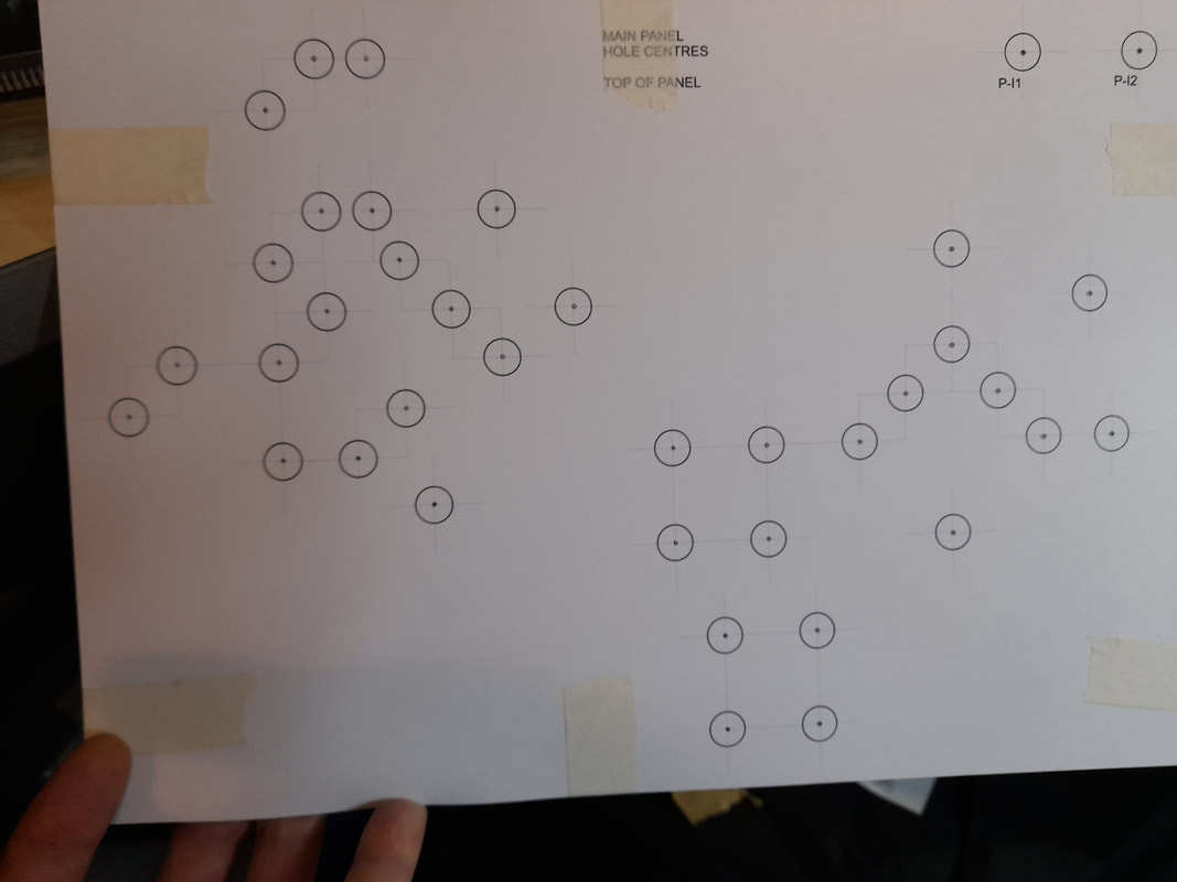
RobertsfieldI have had to hang up the soldering iron for a while, having trapped my thumb in the car boot the other day, I’m having to stick to tasks that can be done with 1½ hands! I have redirected my focus towards the control panel (mechanical aspects) and layout scenic design. The layout will be operated by five control panels across three operating positions – two scenic panels and three fiddle yard panels. Initially it sounds like overkill, but there is method to the madness to provide increased operational flexibility. The two panel types will be identical, so allow for redundancy, but will allow two ‘front of house’ operators to run trains over the whole layout without having to share a panel in front of the layout, while a third operator will be able to shuffle trains in the fiddle yard. This is the main reason for choosing a digital layout control system with pushbuttons; multiple panels can operate the same functions. Below is the plan for the scenic control panel facia: 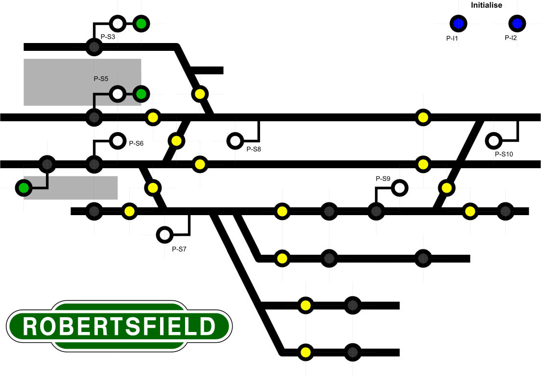 The buttons are all illuminated under specific conditions – yellow are for route setting, green for main signals (lit for ‘proceed’) and white for ground/shunt signals (lit for proceed). The black switches were originally to be non-illuminated for electromagnets, but since I’m changing to servo-operated ‘drop magnets’ I have opted for red illuminated buttons; these will be lit when the servos are not in the lowered position. The last two buttons are the ‘initialise’ buttons, these are pressed simultaneously to get all the CBUS components into a datum status, or ‘start of day’ synchronised setting. The fiddle yard panel is somewhat different – simpler in some respects, but more complex in others. The specific track layout at either end is irrelevant, only the destinations roads and crossovers are needed to be shown. This allows the panel to be reduced in length significantly. With ten parallel roads each over 9-foot-long, and with minimal gaps between them, I have opted to use block detection. Rather than having a panel lit up like a sea of red showing occupied blocks, I will instead inverse the logic and use green LEDs to highlight the vacant blocks, the panel design can be seen below: 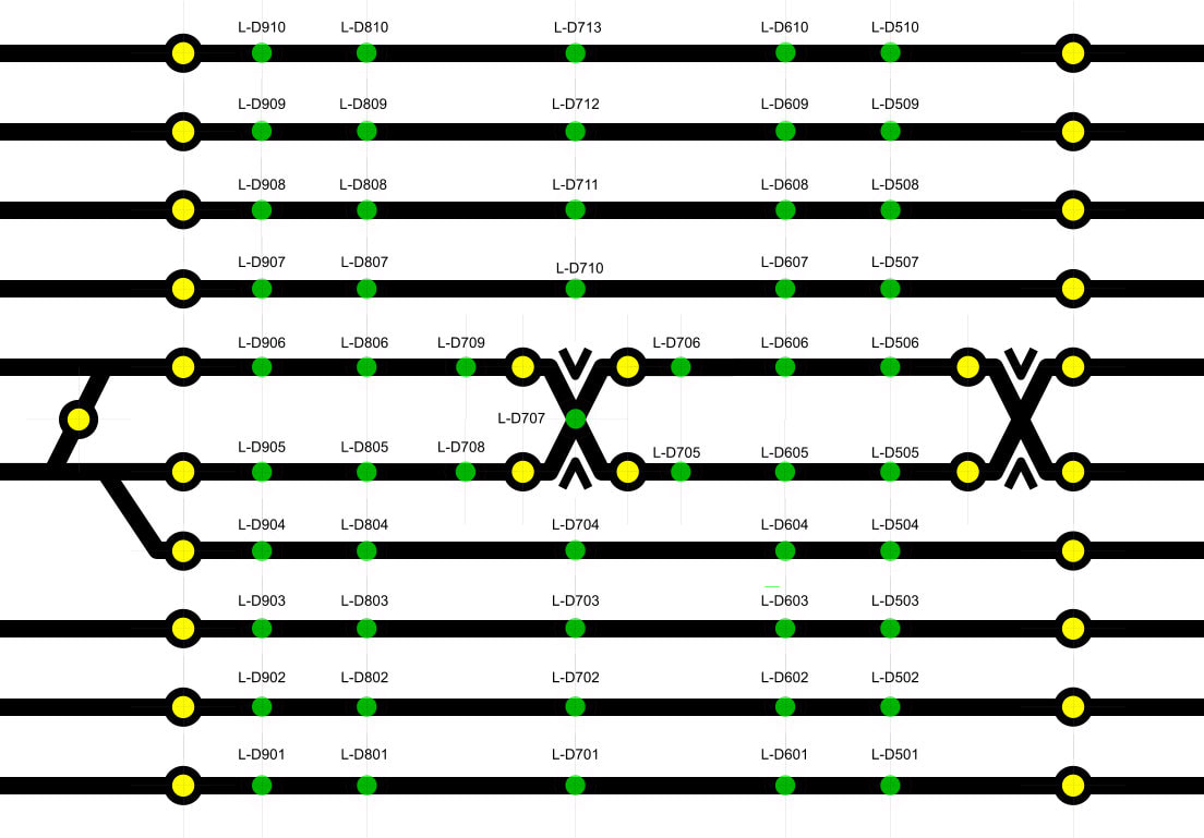 The facias were drawn-up in Xara and will be printed, then laminated and will overlay a sheet of aluminium before fitting the switches and LEDs. I have started by printing a drill guide which will allow me to centre-pop all the holes before piloting and step-drilling to the required sizes: My good friend who built the subframes is constructing the control panel boxes for me. I have also started working on the scenic plan for the layout. I have had a rough idea in mind but thought it about time to start putting some detail into the plans. As I have been doing for my ‘modern’ planned layout Bridgtown, I have imported the Templot file into Xara to draw up the scenic plan. So far, the imported track components have been tidied up; some 20000 plus parts reduced to around 3000 parts, and I have added the third rail. I have also started on a few scenic details, such as board crossings, a few buildings roughly placed and a bit of greenery: 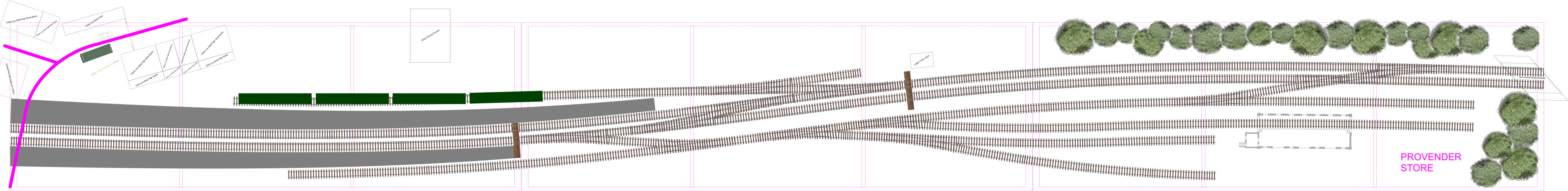 The goods shed is from Aldershot, the footprint re-drawn in Xara from some drawings purchased from the Network Rail Media store. I am looking to make use of the Scalescenes printed kits and have been working on how best I can use them to block views of the roads disappearing into the backscene. It needs some more refinement, but I should get there. Behind the station will likely be house backs and gardens, maybe an electrical sub-station for supplying the third rail. The signal box, which I have started building, is a cut-down ‘Arch Laser’ LSWR type 4 box kit.
0 Comments
RobertsfieldThe wiring modifications continue apace, with a further two baseboards almost complete. This leaves me with the last two baseboards to modify, then any final minor tasks to complete across the layout before the baseboard electrics get 'signed off'. Baseboards 1 and 8 were the last two paired boards to be worked on and the below images show the progress of baseboard 1: 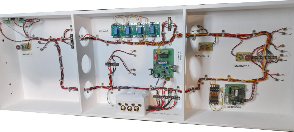 The above image shows the baseboard prior to modification, with the CBUS ACC8 output module, Quad Relay Board, SERVO4 and interface board, all of which were removed as part of the mod programme. The Electromagnets were also to be removed. The CAN bus wiring was also to be replaced with ethernet cable to incorporate an additional power supply for the MERG units. 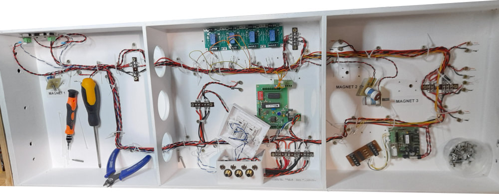 Cable ties were cut and the redundant components detached from the board, the mess begins! 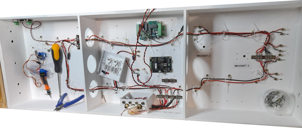 The MERG DCC 'District Cutout' and CBUS CANMIO are installed, new tag strips to alter the existing 12VDC supply and DCC bus are also in place. 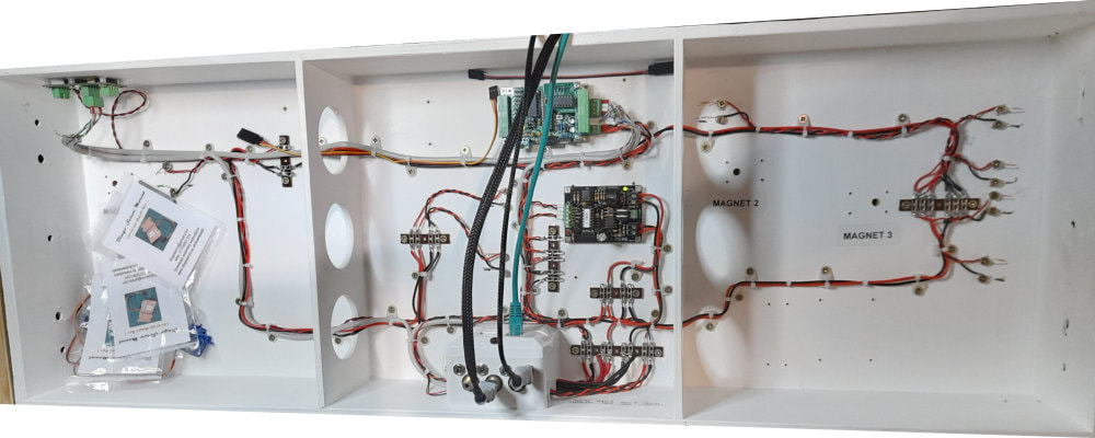 The last image during testing; the CANMIO has been added to the CBUS 'network' in the FCU which is MERG's programme for setting up the CBUS components. Track power has been applied and the DCO overload protection tested. Only the uncoupling magnet assemblies remain to be constructed, signal servos fitted (in the future) and additional component labels to be added. That leaves me with baseboards 2 and 7 yet to modify, and baseboard 2 is the most complex, but hopefully the one to benefit the most from the reduced number of components.
|
AuthorWrite something about yourself. No need to be fancy, just an overview. Archives
December 2020
Categories |
 RSS Feed
