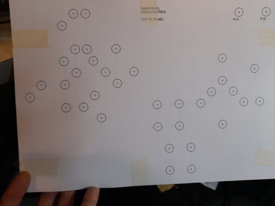
RobertsfieldAfternoon All, and Season's Greetings! I have been continuing to work on both the layout scenic plan and the physical control panels. The scenic plan is (I think) beginning to fall into place now and I have been focussing on avoiding the ‘clangers’ by ensuring the baseboard joins and backscene ‘junctions’ are disguised as best as possible. I’m hoping the scene will give the feel of a small town serving agricultural and light manufacturing industries, but still have a slightly rural feel. 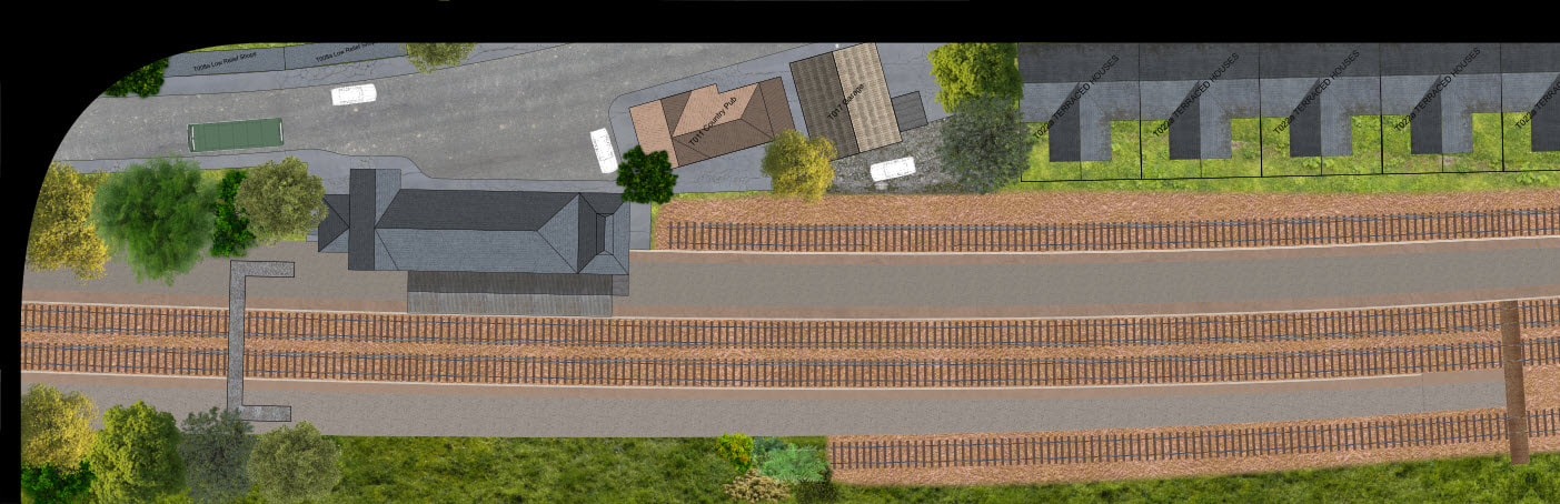 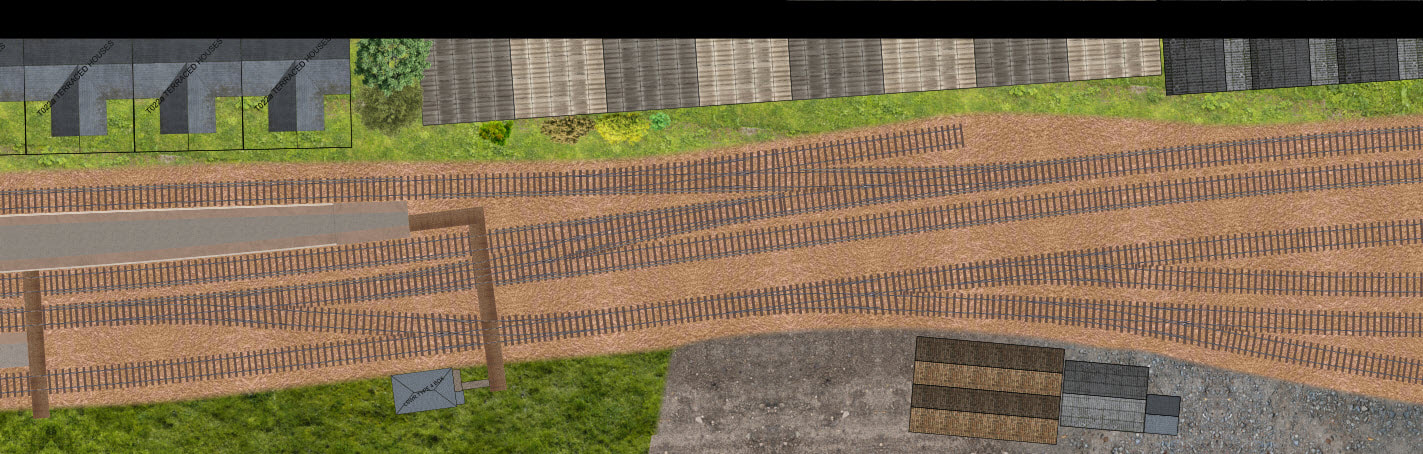 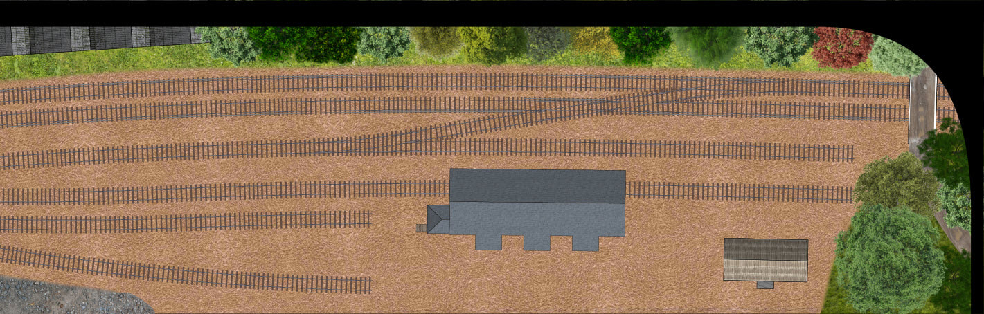 The control panels are progressing fairly well, I have assembled four of the facias with the fifth ready for adding the printed laminates to the aluminium sheet. My friend Rob Cottrell has kindly been working on the panel boxes and a transit/storage unit for them. I need to assemble the MERG units for the panels and then can start installing the wiring, although I’ve recently found that my order for the pushbutton switches was one fiddle yard panel short in quantity, another order to Mouser after payday methinks! I think the panel wiring will be a slow laborious process, and I’ll have to be careful to fully plan and document all the connections to ensure the panels are identical within the types and make the programming as simple as possible later. Below is one of the scenic panels, front and rear view: 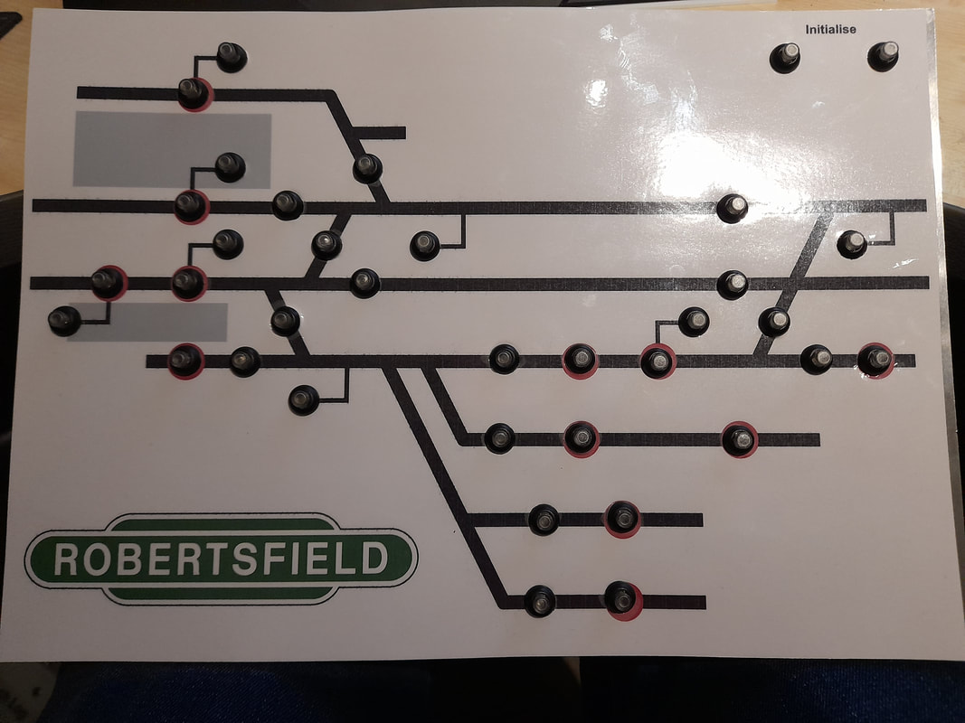 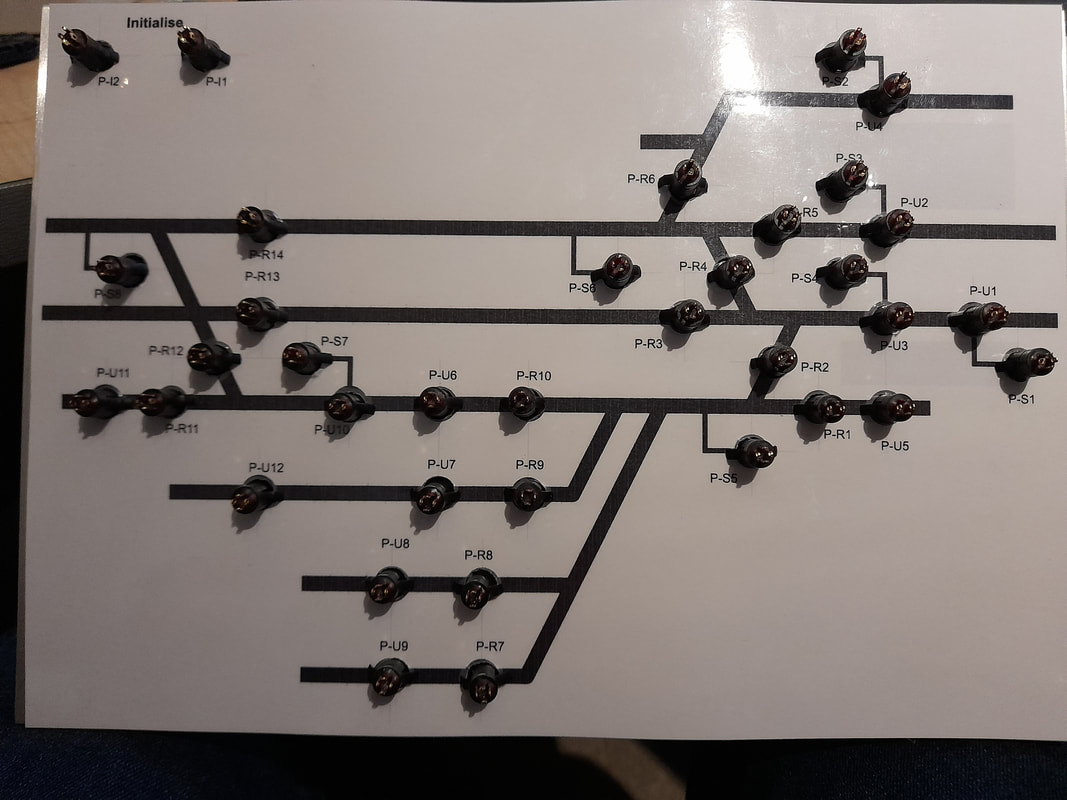 And one of the fiddle yard panels, front and rear view: 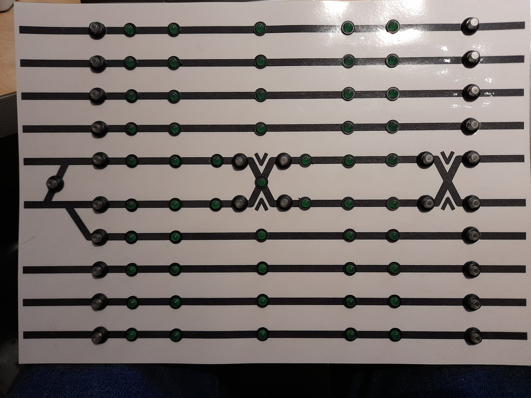 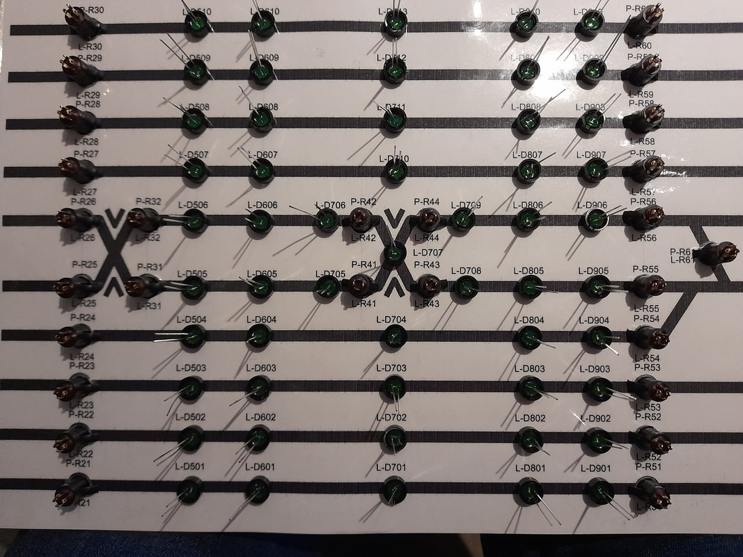  This is the first time I've used aluminium for a control panel, previously always having worked with perspex. Unfortunately the laminated prints don't appear to correctly line up with the holes, I know a few of the holes ended up slightly offset, but not to the extent as seen with the facia on. What I don't understand is why there is such a big difference the expands across the length of the panel when the prints were all from the same document on the PC and the same printer.
Equally, the holes needed for the switches are not as big as advertised in the switch specs document, so there is a bit of wriggle room there. Is it frustrating - yes, will it do the job - yes, so am I going to correct it - certainly not! Probably won't be too much tangible progress over the next few weeks, I've only got a couple of days left to get ready for Christmas (tidying up etc - the shopping's all done!) before I go back to work - night shifts finishing Christmas morning! I've got the last three baseboards with wiring changes to complete so that I can then clear some space around the modelling desk before I attach the panels properly. Cheers, Mark
0 Comments
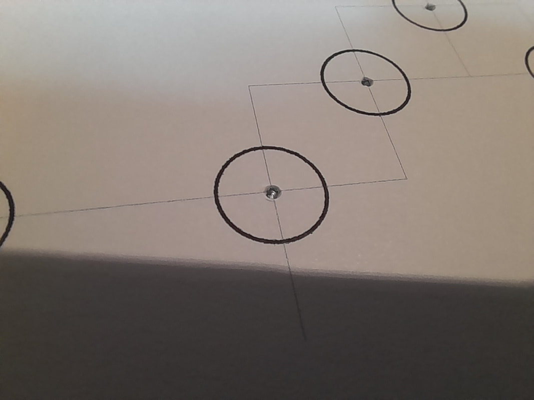
RobertsfieldI have had to hang up the soldering iron for a while, having trapped my thumb in the car boot the other day, I’m having to stick to tasks that can be done with 1½ hands! I have redirected my focus towards the control panel (mechanical aspects) and layout scenic design. The layout will be operated by five control panels across three operating positions – two scenic panels and three fiddle yard panels. Initially it sounds like overkill, but there is method to the madness to provide increased operational flexibility. The two panel types will be identical, so allow for redundancy, but will allow two ‘front of house’ operators to run trains over the whole layout without having to share a panel in front of the layout, while a third operator will be able to shuffle trains in the fiddle yard. This is the main reason for choosing a digital layout control system with pushbuttons; multiple panels can operate the same functions. Below is the plan for the scenic control panel facia: 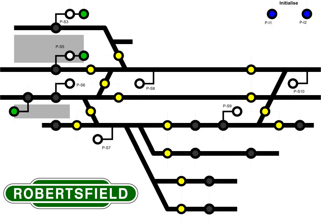 The buttons are all illuminated under specific conditions – yellow are for route setting, green for main signals (lit for ‘proceed’) and white for ground/shunt signals (lit for proceed). The black switches were originally to be non-illuminated for electromagnets, but since I’m changing to servo-operated ‘drop magnets’ I have opted for red illuminated buttons; these will be lit when the servos are not in the lowered position. The last two buttons are the ‘initialise’ buttons, these are pressed simultaneously to get all the CBUS components into a datum status, or ‘start of day’ synchronised setting. The fiddle yard panel is somewhat different – simpler in some respects, but more complex in others. The specific track layout at either end is irrelevant, only the destinations roads and crossovers are needed to be shown. This allows the panel to be reduced in length significantly. With ten parallel roads each over 9-foot-long, and with minimal gaps between them, I have opted to use block detection. Rather than having a panel lit up like a sea of red showing occupied blocks, I will instead inverse the logic and use green LEDs to highlight the vacant blocks, the panel design can be seen below: 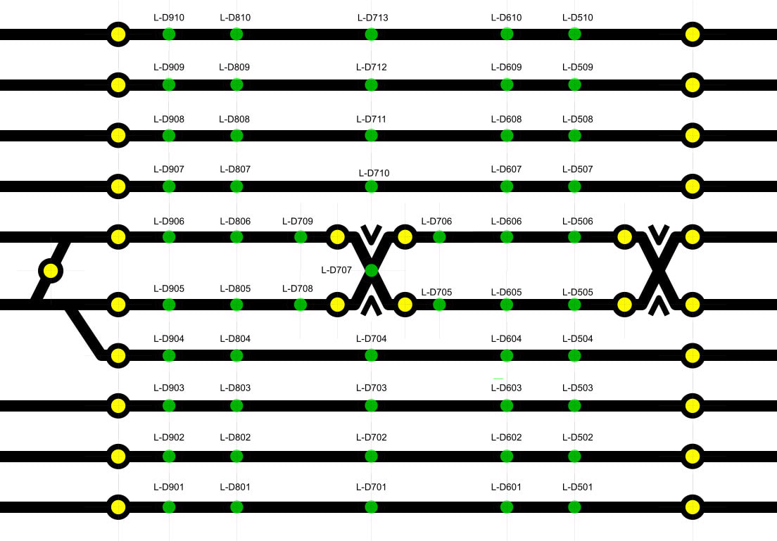 The facias were drawn-up in Xara and will be printed, then laminated and will overlay a sheet of aluminium before fitting the switches and LEDs. I have started by printing a drill guide which will allow me to centre-pop all the holes before piloting and step-drilling to the required sizes: My good friend who built the subframes is constructing the control panel boxes for me. I have also started working on the scenic plan for the layout. I have had a rough idea in mind but thought it about time to start putting some detail into the plans. As I have been doing for my ‘modern’ planned layout Bridgtown, I have imported the Templot file into Xara to draw up the scenic plan. So far, the imported track components have been tidied up; some 20000 plus parts reduced to around 3000 parts, and I have added the third rail. I have also started on a few scenic details, such as board crossings, a few buildings roughly placed and a bit of greenery: 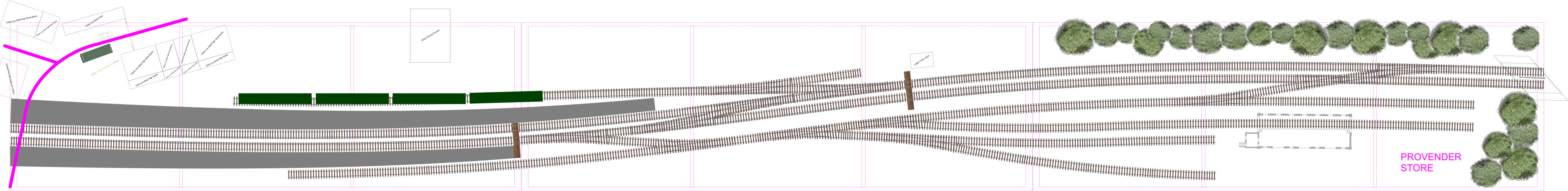 The goods shed is from Aldershot, the footprint re-drawn in Xara from some drawings purchased from the Network Rail Media store. I am looking to make use of the Scalescenes printed kits and have been working on how best I can use them to block views of the roads disappearing into the backscene. It needs some more refinement, but I should get there. Behind the station will likely be house backs and gardens, maybe an electrical sub-station for supplying the third rail. The signal box, which I have started building, is a cut-down ‘Arch Laser’ LSWR type 4 box kit.
RobertsfieldThe wiring modifications continue apace, with a further two baseboards almost complete. This leaves me with the last two baseboards to modify, then any final minor tasks to complete across the layout before the baseboard electrics get 'signed off'. Baseboards 1 and 8 were the last two paired boards to be worked on and the below images show the progress of baseboard 1: 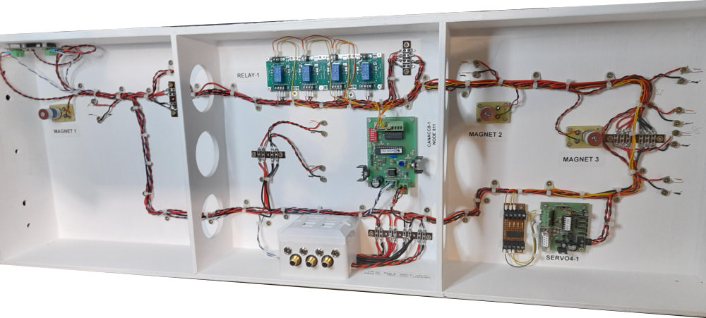 The above image shows the baseboard prior to modification, with the CBUS ACC8 output module, Quad Relay Board, SERVO4 and interface board, all of which were removed as part of the mod programme. The Electromagnets were also to be removed. The CAN bus wiring was also to be replaced with ethernet cable to incorporate an additional power supply for the MERG units. 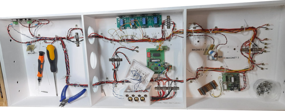 Cable ties were cut and the redundant components detached from the board, the mess begins! 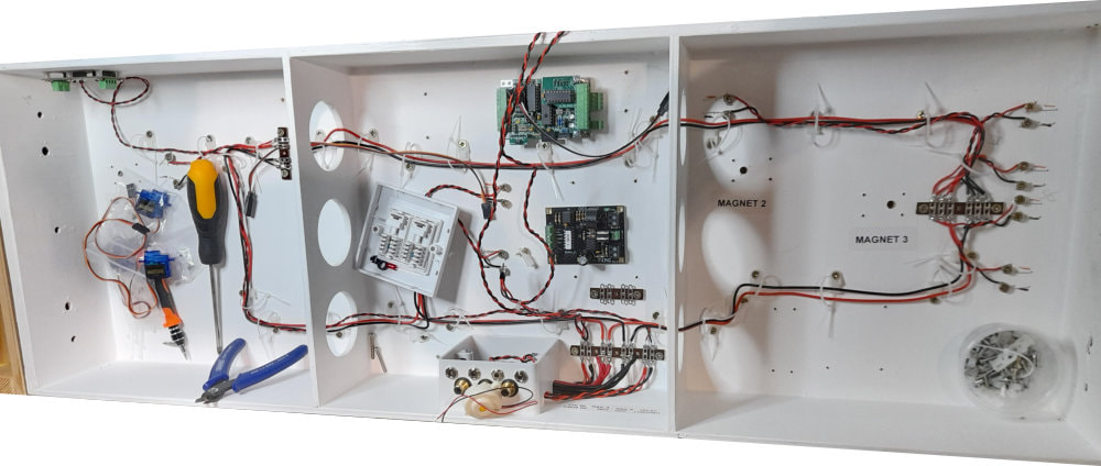 The MERG DCC 'District Cutout' and CBUS CANMIO are installed, new tag strips to alter the existing 12VDC supply and DCC bus are also in place.  The last image during testing; the CANMIO has been added to the CBUS 'network' in the FCU which is MERG's programme for setting up the CBUS components. Track power has been applied and the DCO overload protection tested. Only the uncoupling magnet assemblies remain to be constructed, signal servos fitted (in the future) and additional component labels to be added. That leaves me with baseboards 2 and 7 yet to modify, and baseboard 2 is the most complex, but hopefully the one to benefit the most from the reduced number of components.
RobertsfieldEvening All, Yet again, it’s been another long while since my last update, and for the most part I’ve not done much on the layouts. With all the recent goings on I’ve been in and out of Furlough, and spending most of my time off landscaping the garden or renovating my Brother’s flat. I have recently been helping on a friend’s new 7mm scale layout getting the electrics up running with MERG CBUS and DCC equipment. That is now operable and has spurred me on to progressing my own projects. I have finally managed to get my CBUS equipment working as I intended, although has not been straightforward. Sometime ago I built a small test board to operate two servos from a MERG CANMIO input/output module and receive two inputs from occupancy detectors built to a MERG ‘Pocket Money Project’ design. I couldn’t get the inputs working from the occupancy detectors, the CANMIO not generating any messages on the CAN bus either from track occupancy, or by bypassing with a shorting link on the detector output/CANMIO input. After posting a question on the MERG forum the fix came about by reloading the firmware to the PIC (‘chip’) and then configuring all the inputs channels to outputs, then reverting to inputs. This allowed the bypass link to work, but still nothing from the occupancy detectors. I subsequently found a wire link missing from the detector boards and after checking my working drawing it transpired, I had omitted the link from my drawing. The problem then was that I had assembled around thirty of these dual-detector boards to the incorrect drawing! I am now in the process of modifying these boards and reinstalling them to the fiddle yard baseboards. In addition to the above task I am also making some other changes to the electrics; myself and two other friends are all building layouts that use MERG CBUS and DCC control equipment, which means that we can share equipment for backup purposes. This of course requires a set of standards to ensure compatibility. During the initial planning discussions and research on the MERG website the first two layouts were not configured the same. I am now in the process of revising the CBUS connections to match those of the second layout, the third layout already having been wired matching the second. I am also adding a separate 12V DC supply for the MERG equipment whilst retaining the existing 12V DC supply for the servos and larger loads. I am pleased with how the CANMIOs are working and will take the opportunity to free up some space under the scenic baseboards by switching the control equipment and uncoupling devices. For example, on baseboard 2 (the centre scenic board) I have 3x CANACC8 8 channel output boards, driving 4x SERVO4 boards via optocoupler interface boards, and also driving two quad relay boards. With all the turnout/signal servos and uncoupling magnets this does not leave much real estate spare and the scenic boards also need District CutOuts (DCOs) installing. I will be removing the existing control equipment and replacing with CANMIOs, where two boards will replace 11 existing boards. On top of this I will be removing the electromagnets and associated relay boards and use servo-driven drop magnets which are a direct drive from the CANMIOs which will save even more space. So far, I have completed two baseboard conversions, and two nearly completed. I have also produced a test control panel in JMRI show below, which allows me to get all the CBUS configuration completed and satisfactorily tested before I build physical control panels.  Things have changed in the world a bit since my last update, while I've had some time off work I decided to build a scenic test track, having seen a similar project on RMweb. It is basically a double loop forming and inverted figure of eight, using Kato super-elevated double track in the smallest and largest radii: 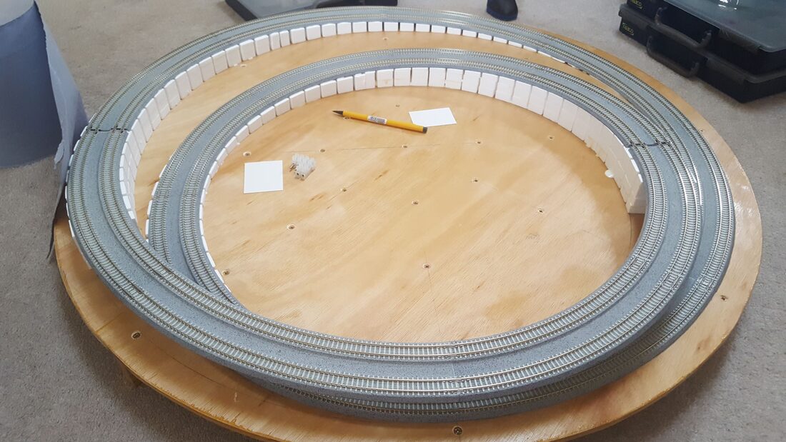 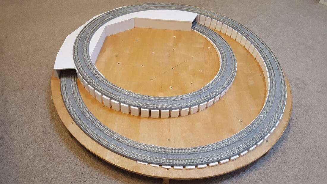 I have used Woodlands Scenic inclines and risers to speed up the build, and foam-core board for the tunnel section. I then used expanding foam to build up the scenic form: 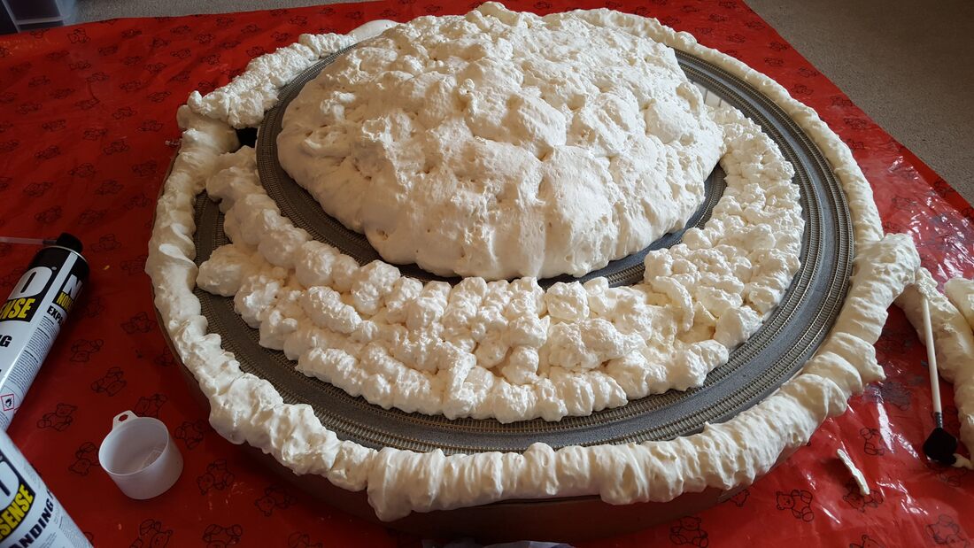 which was then carved and covered in plaster: 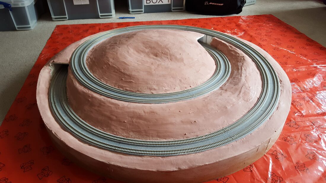 Tunnel mouths were added from the Scalescenes range, printed slightly over-scale due to the wider Kato track spacing, and installed after extending the tunnel structure: 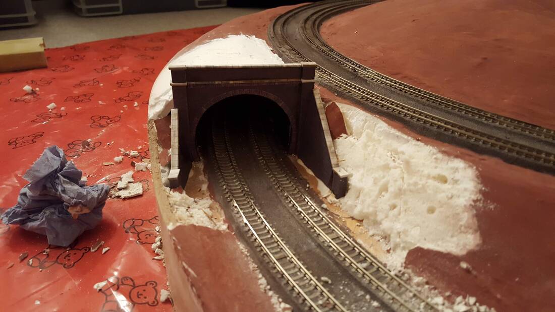 I then added WWS Static Grass: 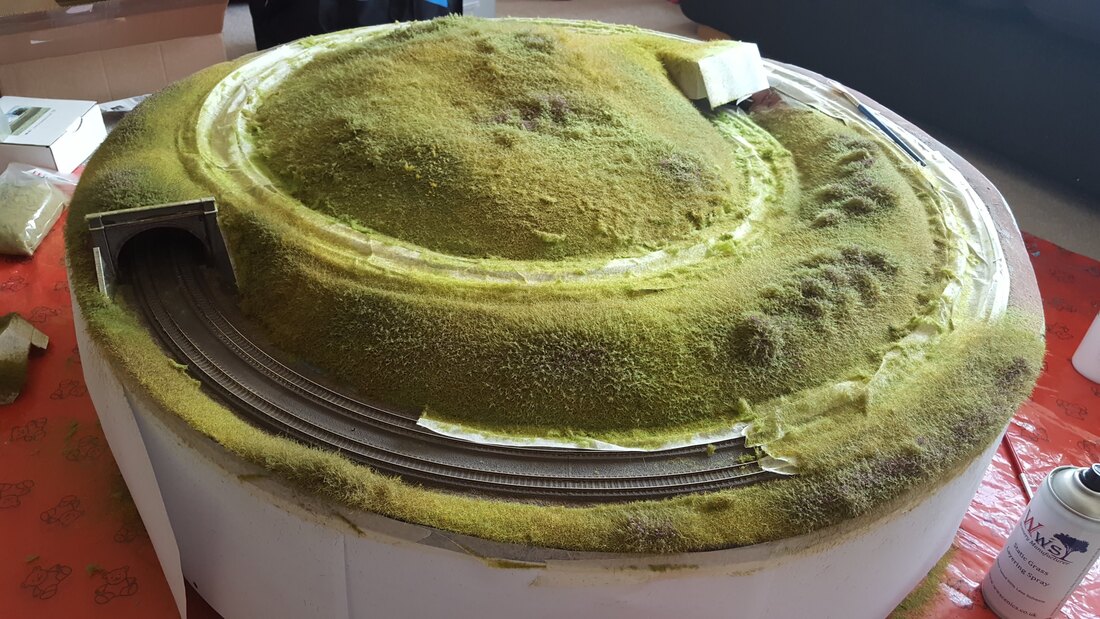 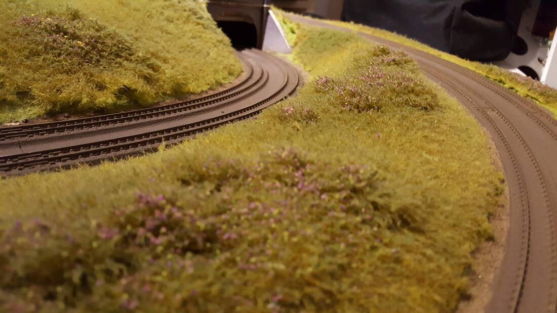 This has given me somewhere to run in new loco's, plus give them a 'routine' run every so often while the other layouts are built.
Cheers, Mark BridgtownSo, it’s been a fair while again since my last update – Christmas has been and gone and we’re in to 2020. Not a great deal has happened – a few boxes have arrived with various rolling stock manufacturers’ latest releases, but possibly the most significant delivery was on Christmas Eve. Santa, cunningly disguised as the local Postman, dropped off a nice parcel from British Finescale containing: 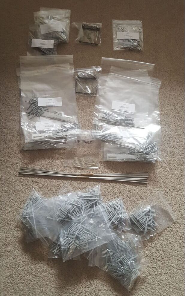 This was my two pledges worth of kits and jigs, which covers the scenic trackwork for the layout; now I just need the time, space and money to get the baseboards ordered.
The previously mentioned changes to the track alignment for using the British Finescale products has led to a review of the scenic plan, and revisions to accommodate the changes. This is currently a work in progress, and probably will be for some time as it is a very time-consuming process. The Templot plan has been imported and ‘tidied up’, I am now adjusting the scenic elements around it. Some of the tweaks are just that – to fit correctly around the realigned track, some others are a little more substantial, such as re-positioning roads. The latter is part of my plan to avoid the road disappearing into the backscene, and to obscure all scenic ‘exits’ as best as possible. I'll upload some images once I've made progress worth sharing. This of course also means the scale mock-up will need revising and will probably be better to start from scratch on that; I can hopefully reuse the buildings though. Anyway, better get on, I’ve got tea to drink, layouts to plan and build… Cheers, Mark BridgtownA quick update from a small amount of work completed a few days ago, I have added the enclosed viaduct arches to the model behind the derelict factory site and added the retaining wall to the rear of the station area. I have also added the platforms and raised ground level where the station building will sit: It’s not easy to see in the photos but the arches and retaining walls all have the detail where the final articles will have a lot more 3D relief. The retaining wall is based on the style at Wolverhampton along the North side of the station by Sun Street and the Great Western Pub – see the below screen grab from Google Maps: 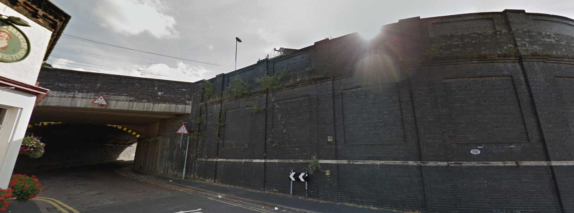 This extends approximately half way along the length of the station before changing to a more ornate design with arches, although I will probably omit the arches on the layout given that it will not be easily seen.
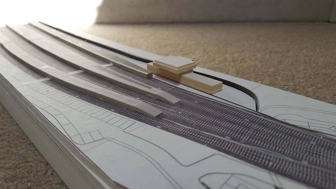
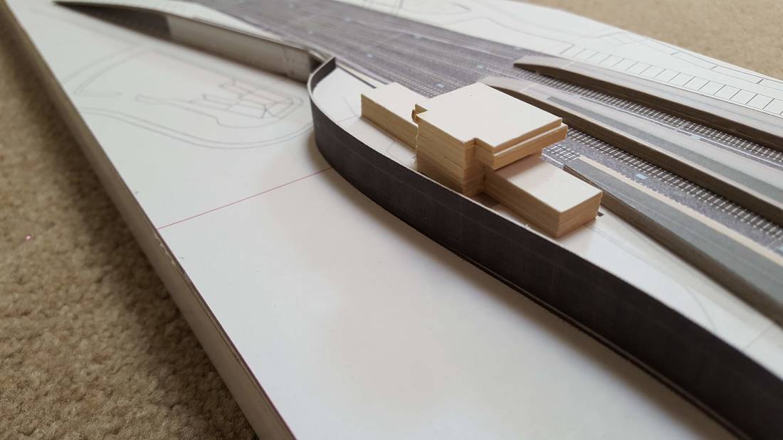
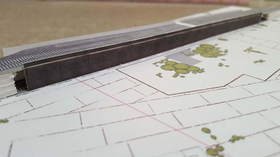
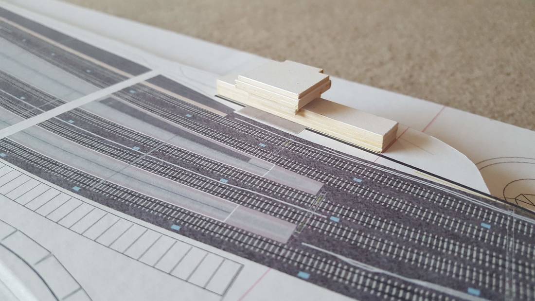
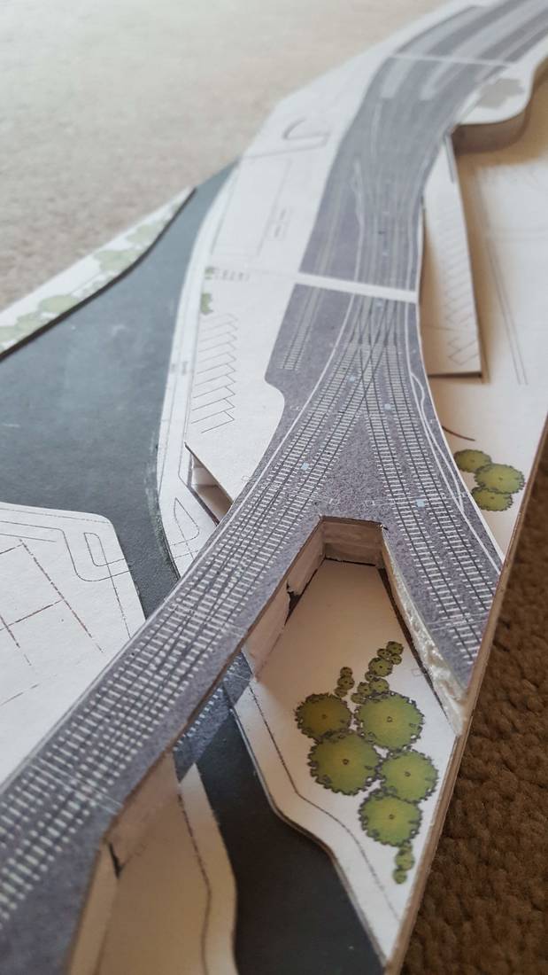
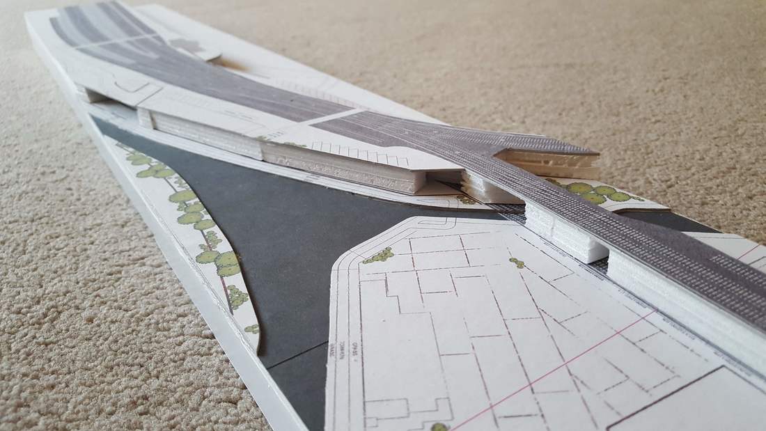
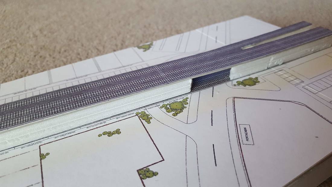
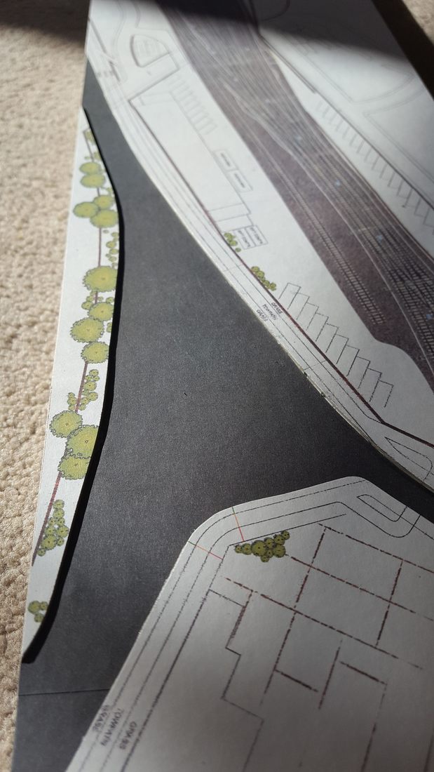
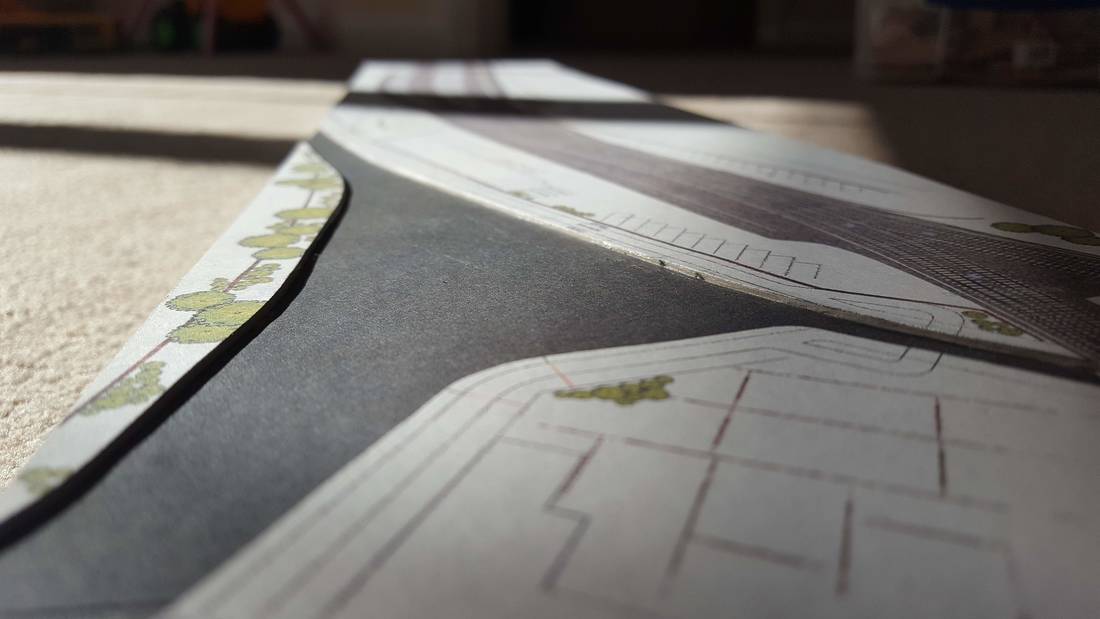
I think my next tasks will be to finish the retaining walls and bridges to complete the raised track areas, then look at finalising the ground levels and roads before adding more buildings. Cheers, Mark BridgtownA quick update before work; to get a better feel for how the layout might/should look, I decided that I would construct a scale mock-up. I have made a reasonable start now, having assembled the base, first and second ground layers and track layer. It’s already starting to give a good impression, and I’m feeling quite positive about how the plan is coming together: Next up will be to add some scaled Scalescenes sheets to show the viaduct arches and bridges, and start making some of the scaled buildings. I’d also like to get the ground levels finished where the road rises from the underbridge to cross the canal.
BridgtownI have made some revisions to the RH Rear scenic plan, having considered how the buildings would sit against the backscene, and more importantly how the gaps between the buildings would give a clear view of the backscene. I think that an undisturbed row of buildings as "modern" medium-sized retail outlets (Halfords, Screwfix etc.) should look okay, and will better disguise the backscene/join. Anyway, this is what the plan looks like now: 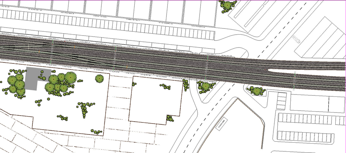 Still not had a chance to start on the scale model yet, but hope to do so soon.
Cheers, Mark BridgtownI have now revised the platform road alignments and updated the Xara scenic plan to incorporate the changes. The scenic plan has now developed, with the inclusion of more building outlines and scenic details: The left-hand end of the layout has seen little change, apart from correcting the track and platform alignments: 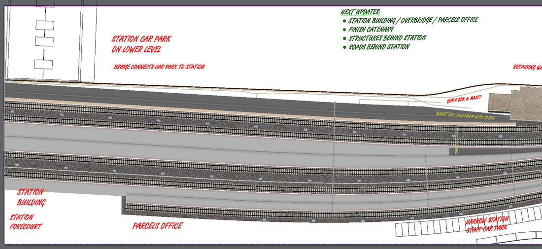 Plans for the station building and overbridge have been started in a separate file, which will be incorporated in the overall layout plan once developed further. All the buildings are being planned in a similar way – created in separate files, then copied into the overall design: 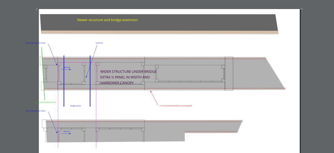 The centre-left section has seen some realignment of the roads, the addition of a part-derelict office building in the network Rail yard, and a lot more detail added: 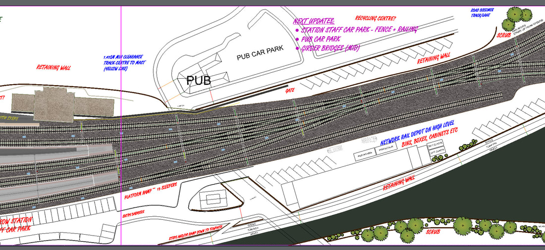 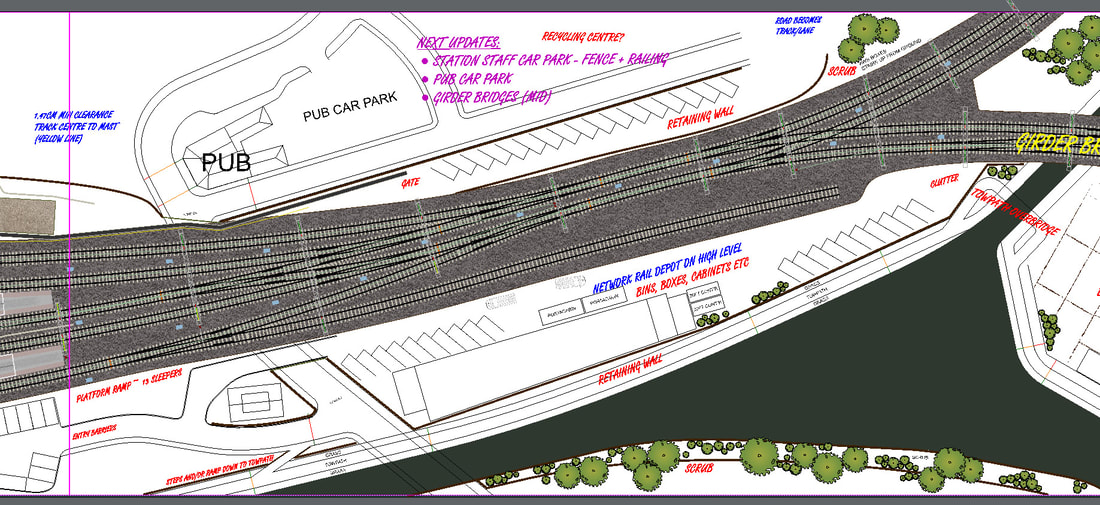 The centre-right section has had more detail added to the derelict factory site to resemble the concrete sectional ground cover, old foundations and overgrown appearance: 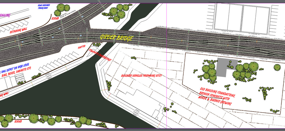 The right-hand end has seen the development of the industrial area around the railway with the addition of Scalescenes Industrial units for retail outlets behind the viaduct. I also plan to model a building that will be based on a tired-looking structure I spotted between Terminals 3 and 5 when working at Heathrow, that is packed with detail and character. In front of the viaduct/embankment will be a structure based on the demolished “Bradburn & Wedge” building that used to be on Darlington Street in Wolverhampton. It will be modelled as offices rather than a car retailer, so smaller windows on the ground floor. Filling in the gap between the main and service roads will be a small car repair/MOT test facility, with all the clutter and paraphernalia that accompanies: 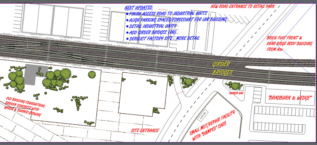 I now have some A3 foam board, so plan to start assembling a scale mock-up fairly soon.
Cheers, Mark |
AuthorWrite something about yourself. No need to be fancy, just an overview. Archives
December 2020
Categories |
 RSS Feed
