Chelsey Street
Electrics
I am sticking with my favoured DCC and layout control systems from the Model Electronic Railway Group "MERG" - DCC version 2 and CBUS. All the DCC control equipment is common to all my DCC projects which is a great way to save costs.
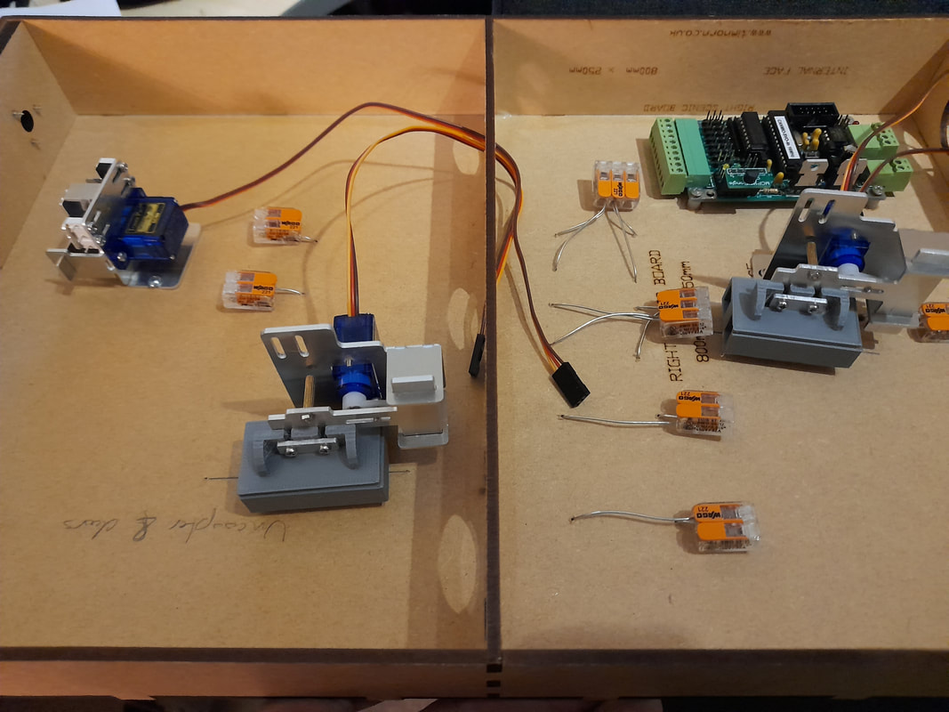
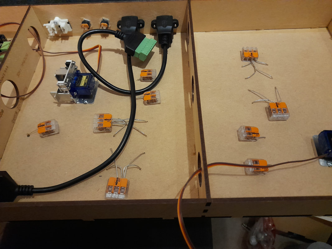
Something I am trying out on this project is the use of Wago connectors for the DCC bus, which will allow quicker installation, plus an easier way to isolate sections of track for troubleshooting short circuits.
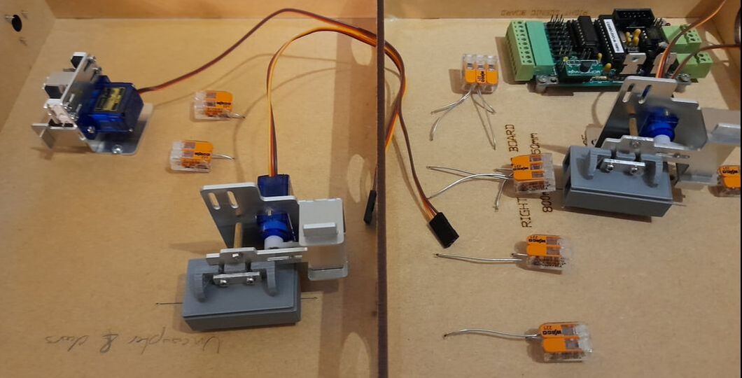
Baseboard 2, with Wago connectors fitted to the track droppers.
This layout is using 9g servos for turnout operation again, but this time fitted to Dingo low-profile servo mounts. I am also using the Dingo servo uncouplers. These are being driven by CANMIO with the basic servo firmware.
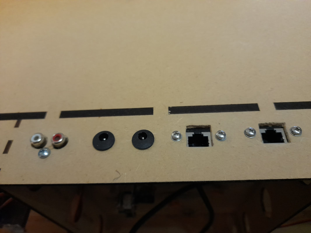
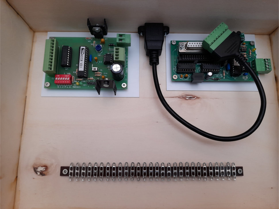
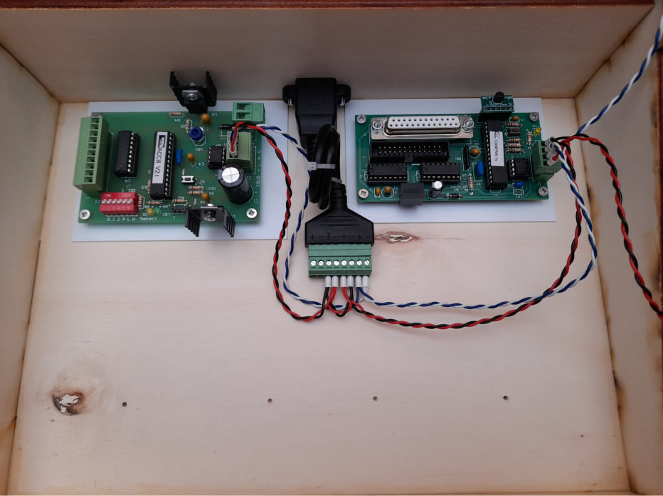
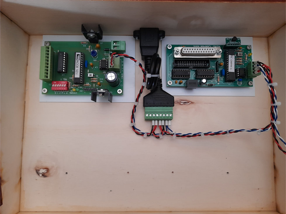
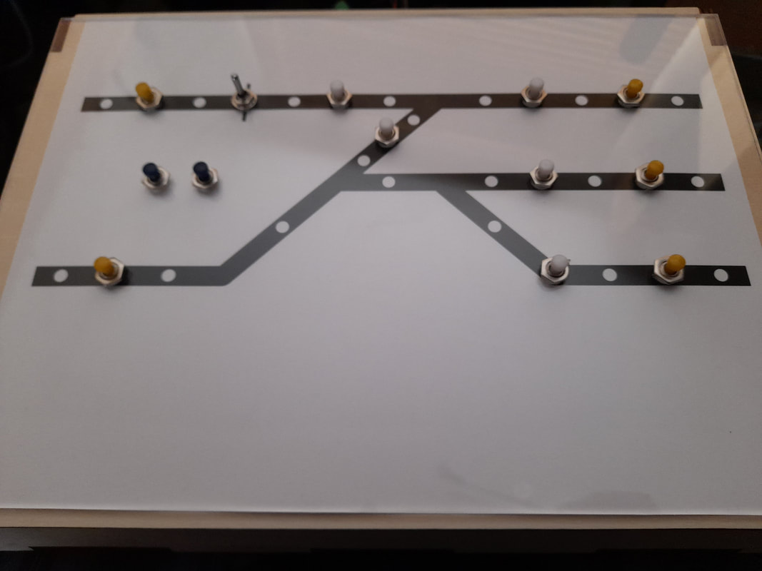
The control panel uses a Model Railway Solutions kit that I happened to have lying around (as you do), and is probably massively oversized for such a simple track plan, but allowed plenty of space for the CBUS equipment inside. The panel facia is clear acrylic sheet over a printed layout plan that is then overlayed on the control panel front. Switches are fitted to the acrylic with clearance holes through the ply panel front, and low-current LEDs are fitted to the panel front but behind the printed plan and held in with hot glue.
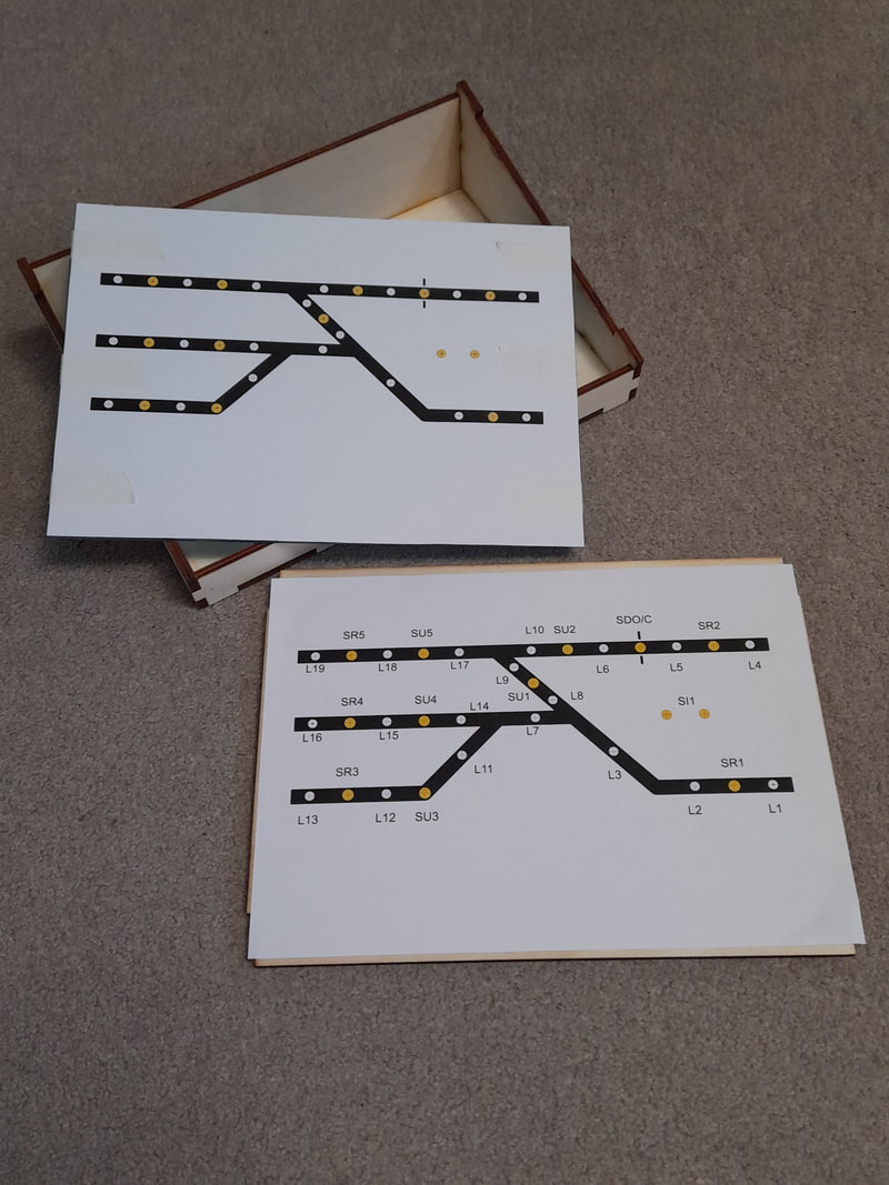
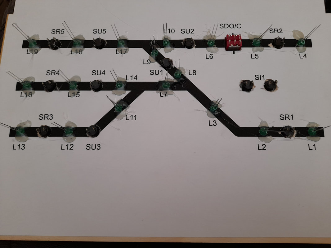
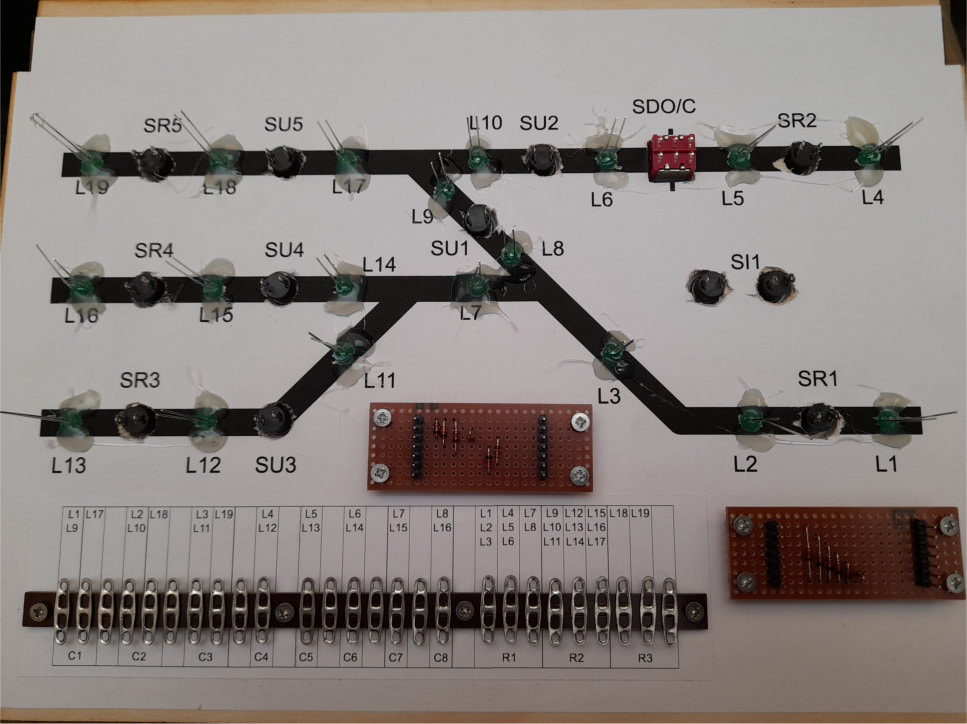
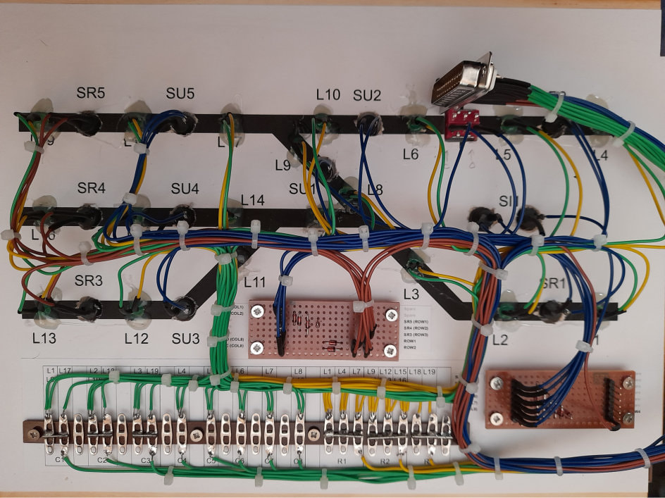
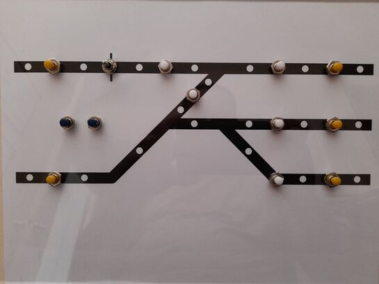
The rear face of the panel front has the plan printed in reverse with all components labelled for ease of identification.
The rear face of the panel front has the plan printed in reverse with all components labelled for ease of identification.
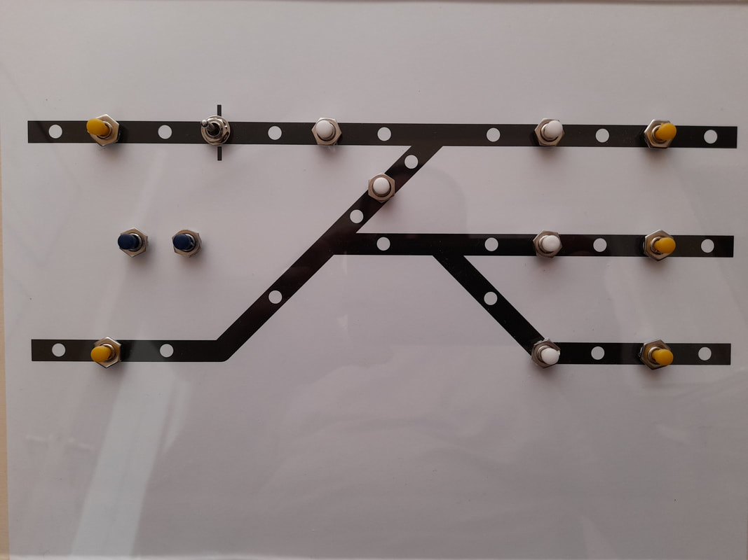
The control panel facia - a printed schematic plan overlaid with Acrylic sheet.
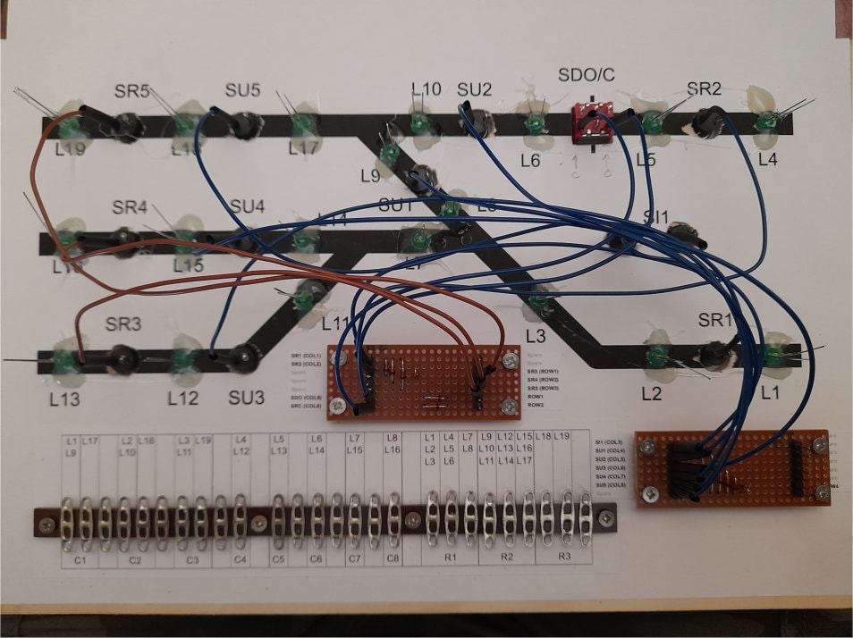
The yellow pushbuttons will set the routes in an entry-exit (NX) style, with the two buttons forming a route having to be pressed simultaneously. This will trigger a CBUS 'Event' from a CANPAN module to cause the route LEDs to flash and set the turnouts as required. Once the servos reach the required positions, the CANMIO sends further events out on the bus, these will be detected by a CANACC8 running CONCOND firmware. Once the correct events are all detected by the CANCOND, it will then send another event which will be picked up by the CANPAN and set the LEDs to a steady state.
The white buttons operate the uncoupling magnet servos and the two blue buttons also connected in series trigger the Initialise, or "start of day" CBUS event. This simply sets the layout components and LEDS to a predetermined condition such that the layout and panel are in agreement.
The toggle switch is intended to operate a couple of servo-driven doors, or possibly gates depending on what I can fit in scenically.