Robertsfield
Electrics
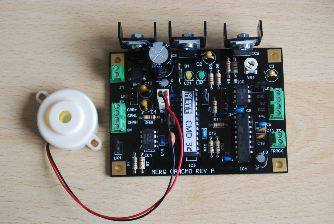
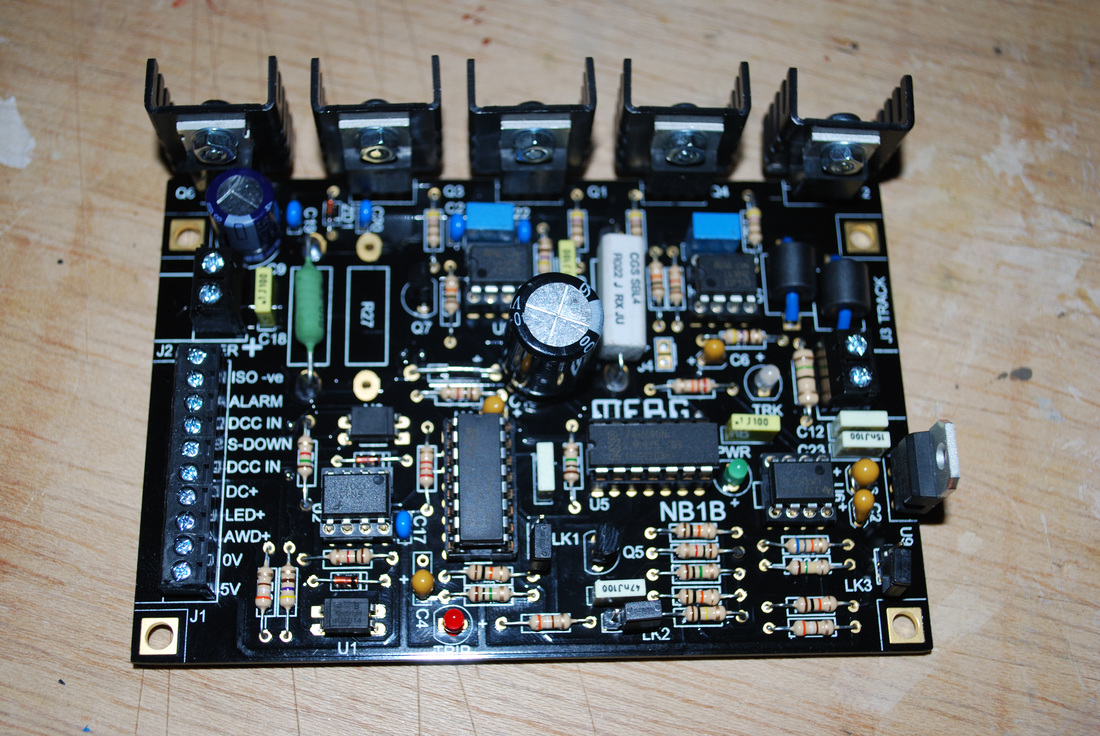
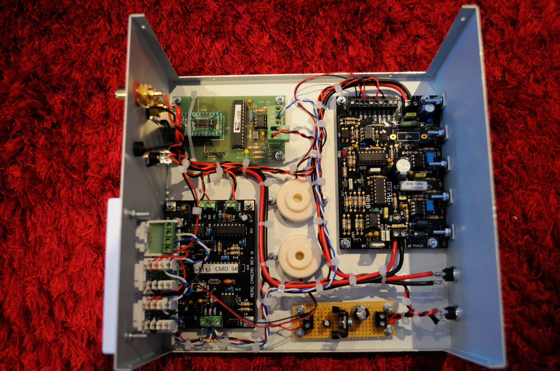
Robertsfield will use a DCC control system for controlling the trains, and I have opted to use the Model Electronic Railway Group "MERG" version 2 system. I have tried various systems previously, and never found a handset that I particularly liked. They were either a nice size, but lacking functionality; or overly large, with too many controls than are really needed for basic 'playing trains'. With the Digitrax system, I don't like the small rubber buttons, and the more compact throttle has the very un-ergonomic encoders for changing loco address. Equally, I'm not keen on the Lenz system where you either get a throttle with a full numeric keypad, but speed control via buttons (which I really don't like!), or a rotary speed controller, but with limited keypad.
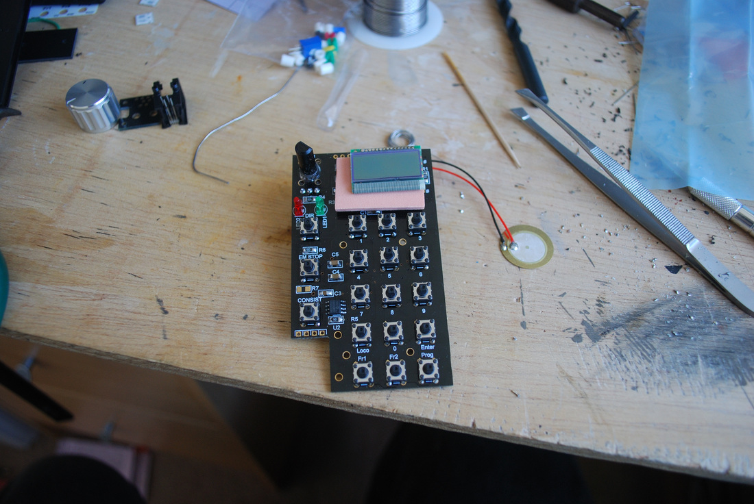
I find the MERG CANCAB is a very nice ergonomic design, that encompasses all the features that I sought.
I find the MERG CANCAB is a very nice ergonomic design, that encompasses all the features that I sought.
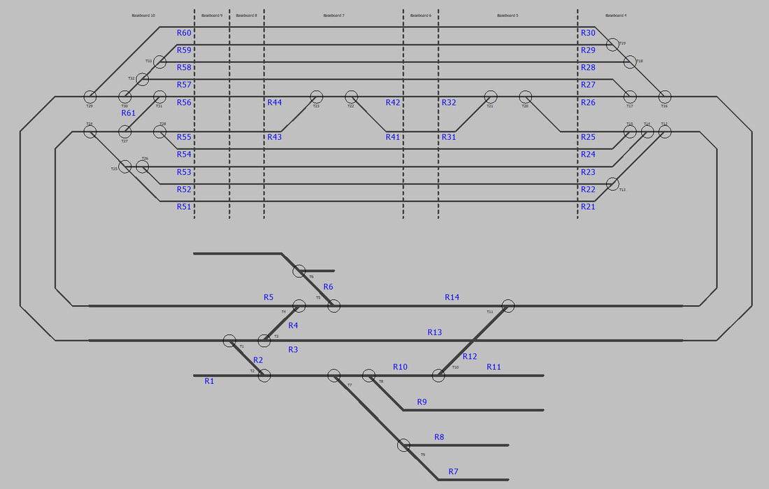
The control of the layout itself, i.e. the turnouts, signals etc. will utilise the MERG CBUS system. Again, i find this a very adaptable system that works very well. It is far more cost effective than 'off-the-shelf' digital products, and allows far more flexibility than a basic analogue control system, such as running two control panels with overlapping controls.
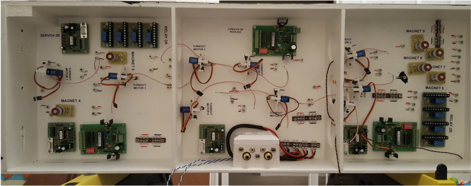
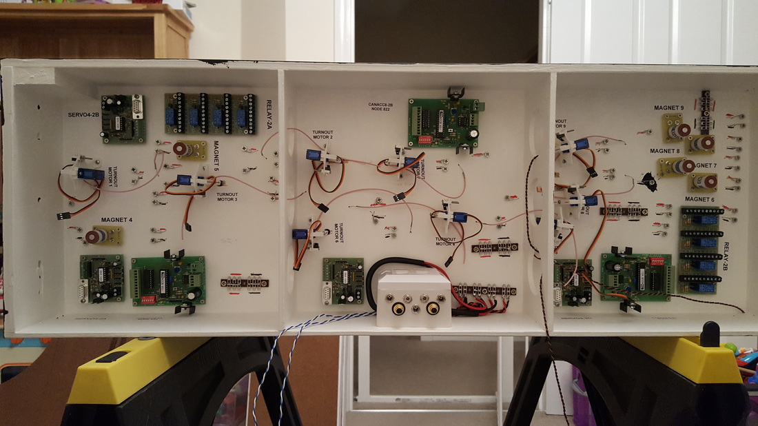
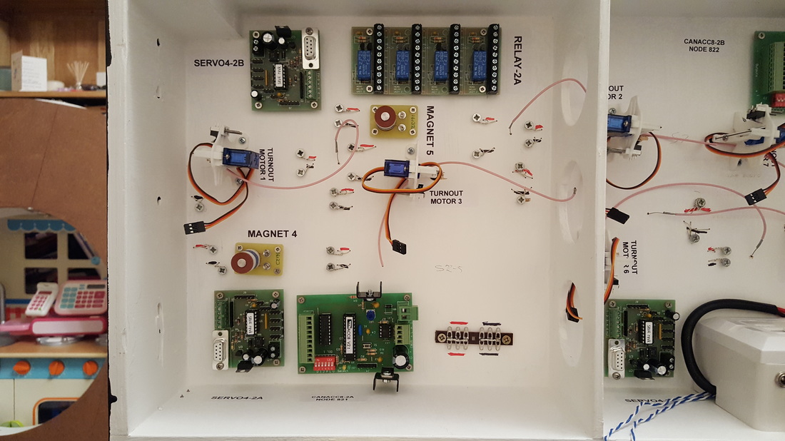
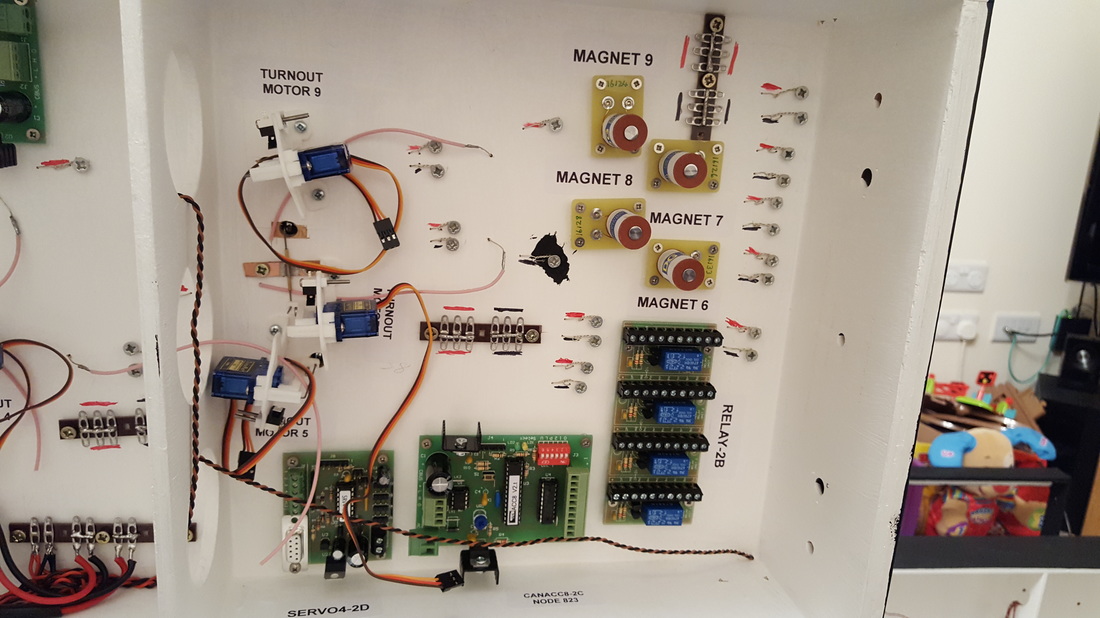
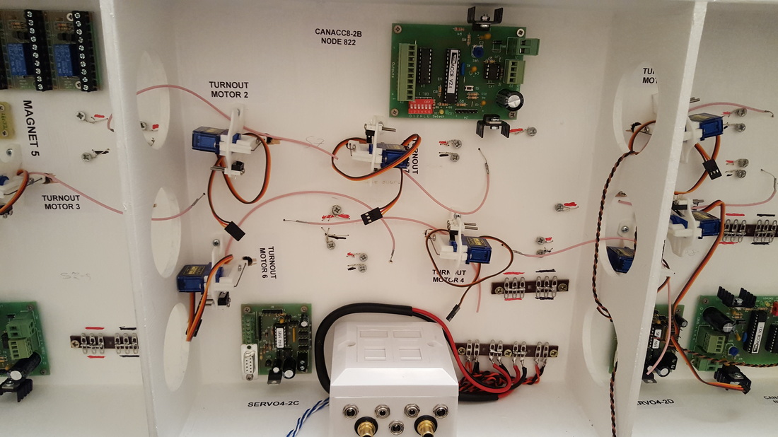
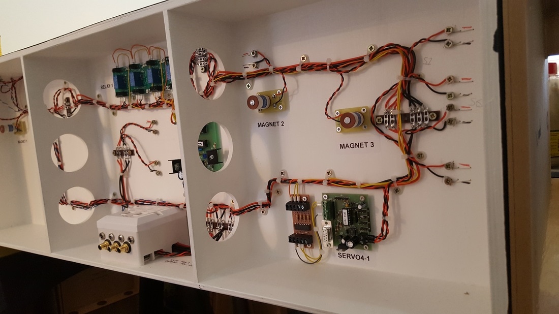
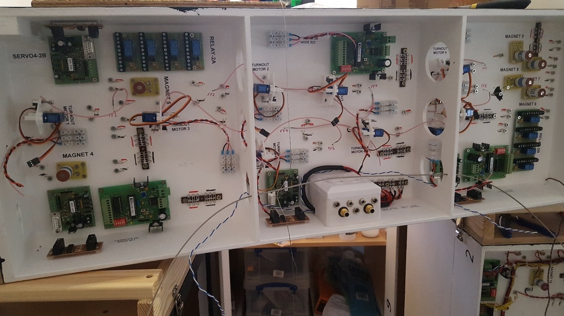
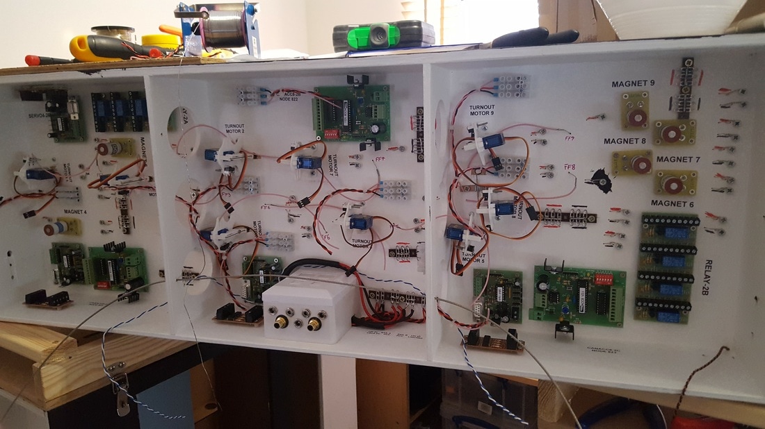
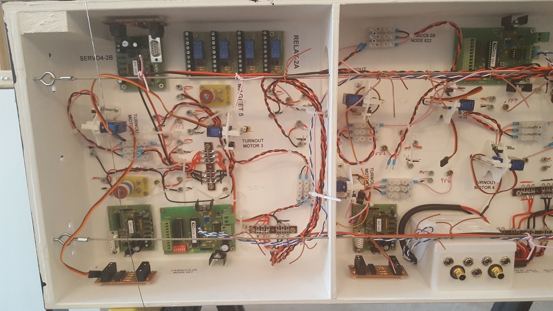
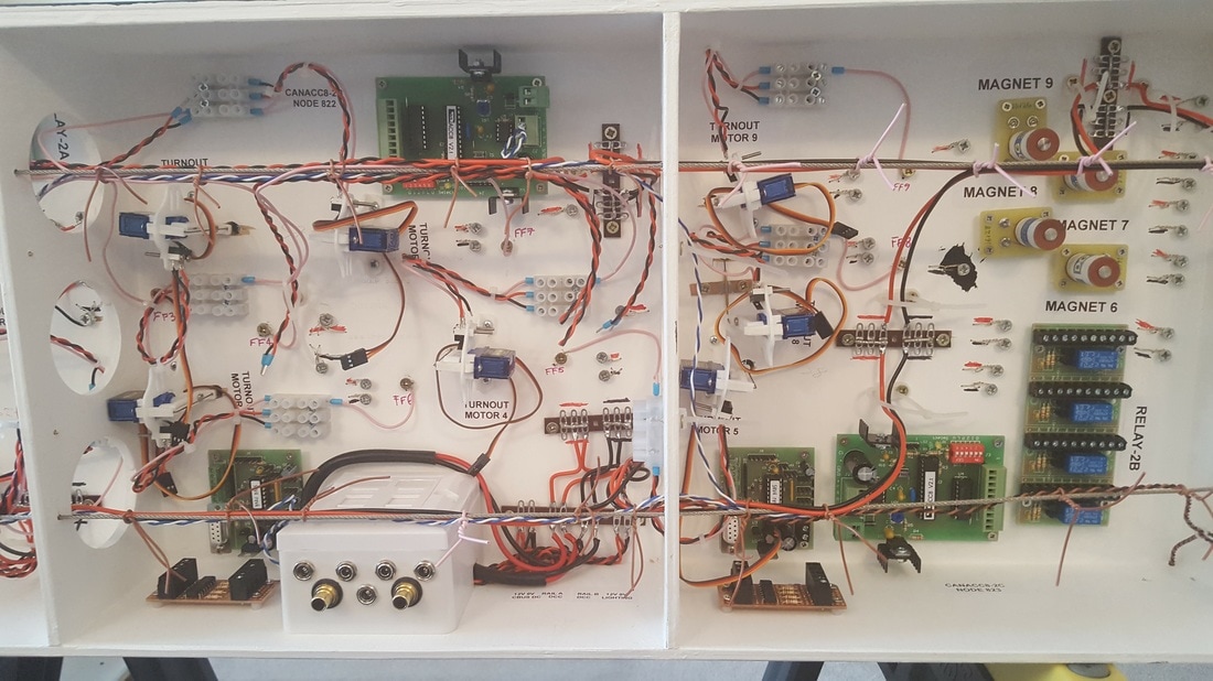
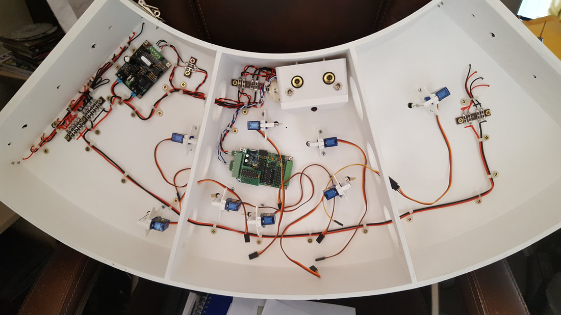
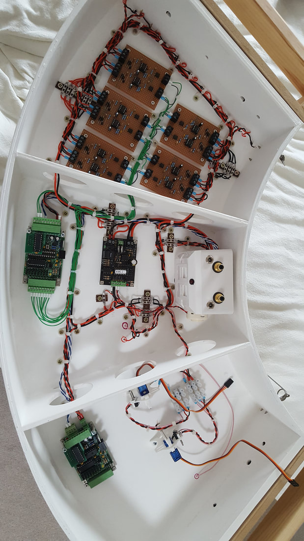
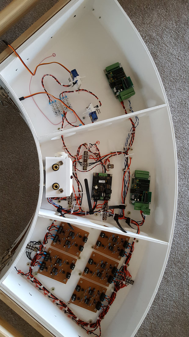
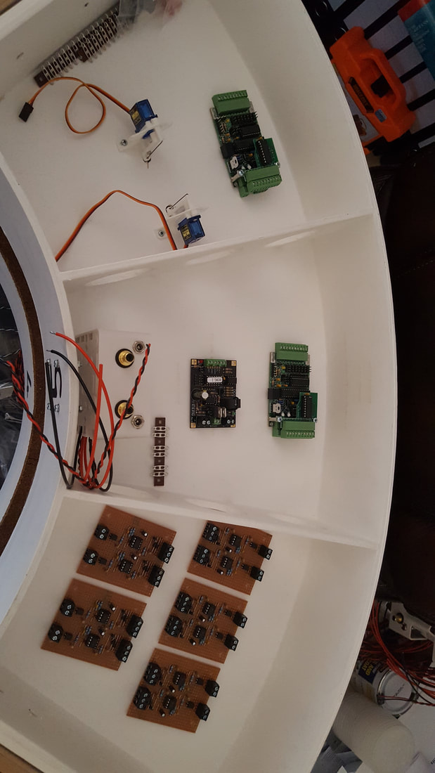
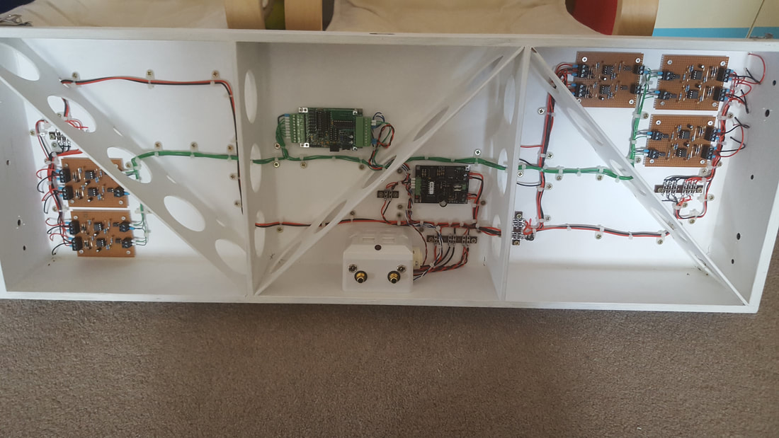
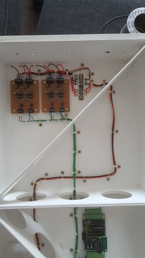
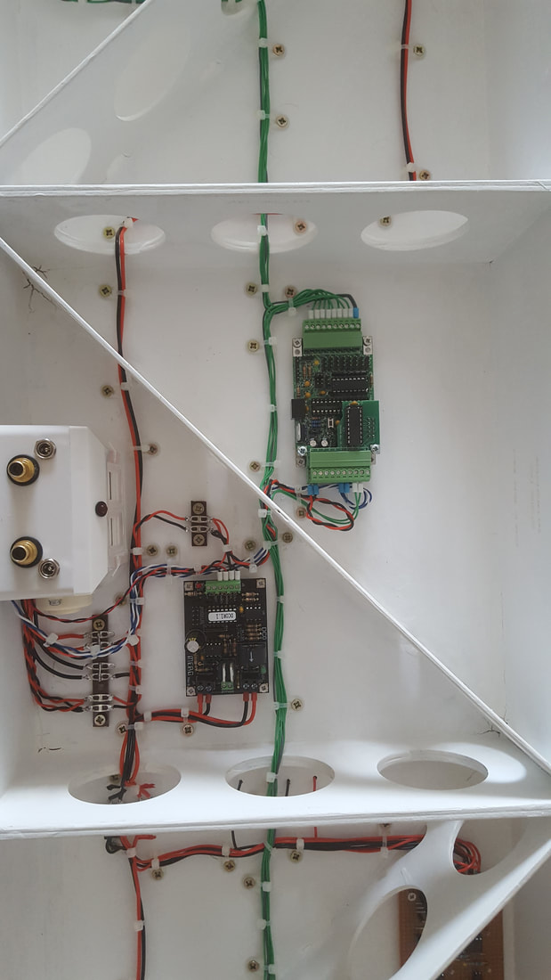
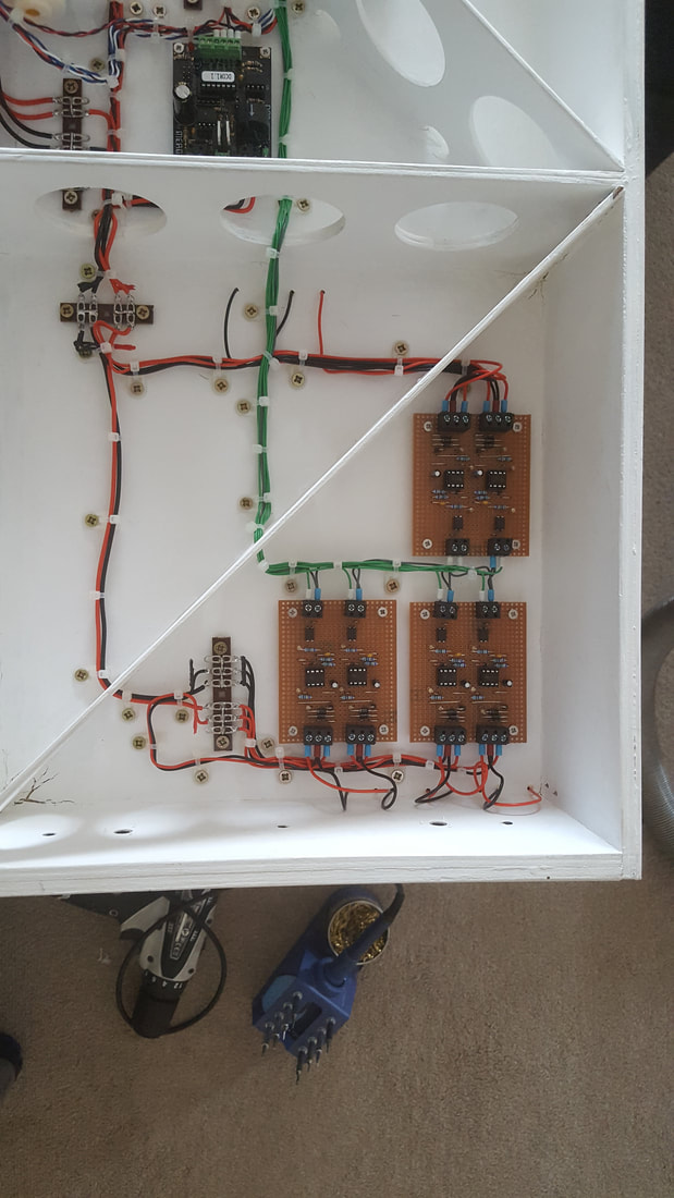
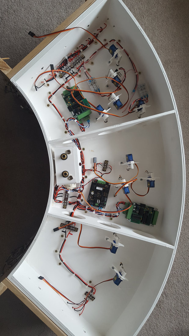
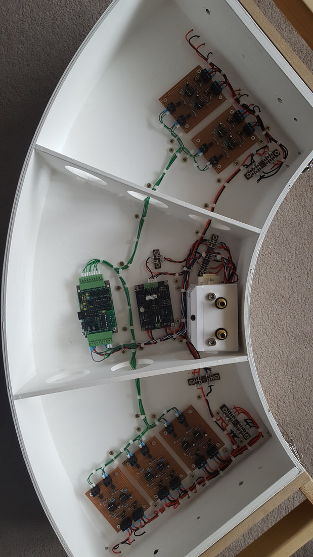
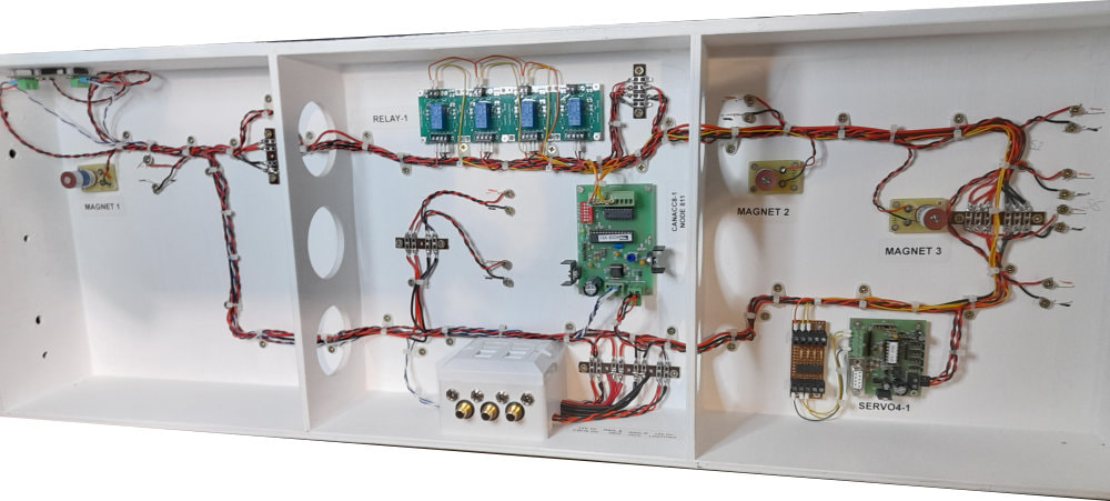
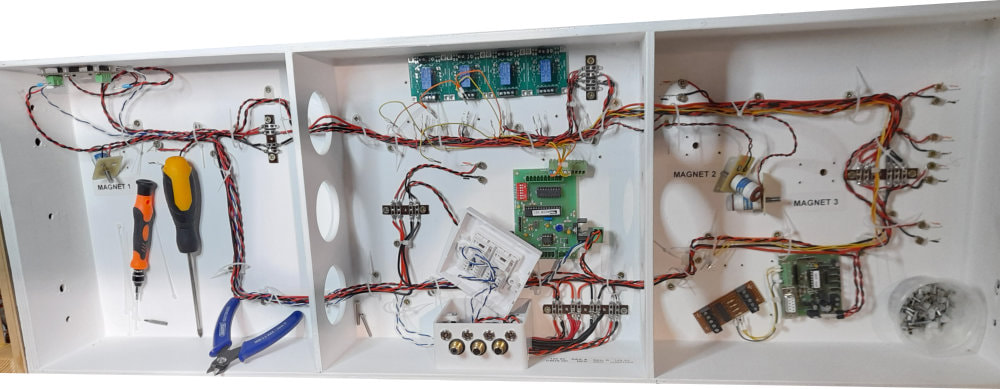
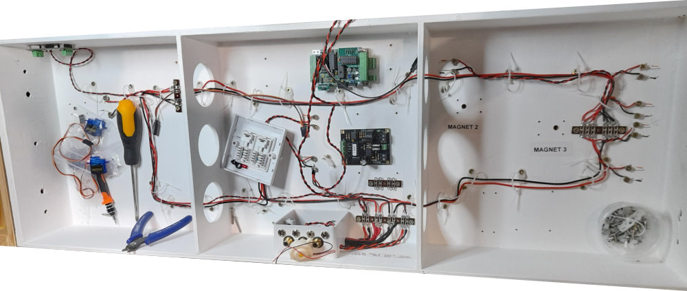
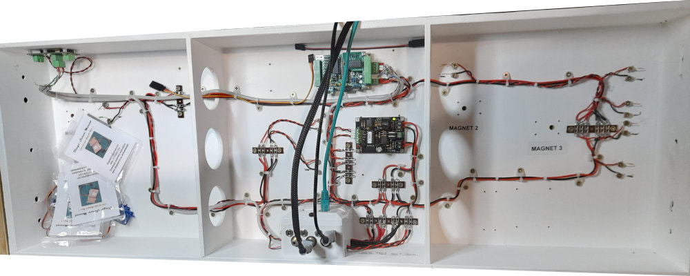
Baseboard 2, with all components fitted, except the signal servos.
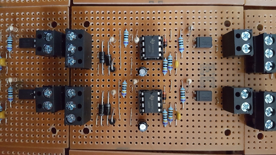
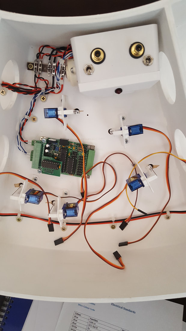
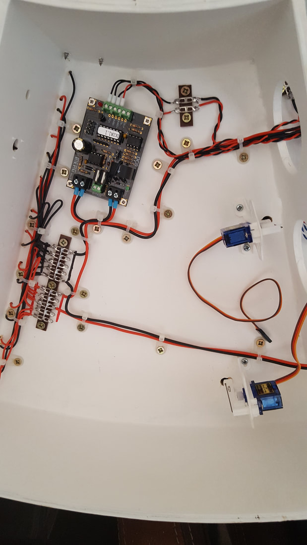
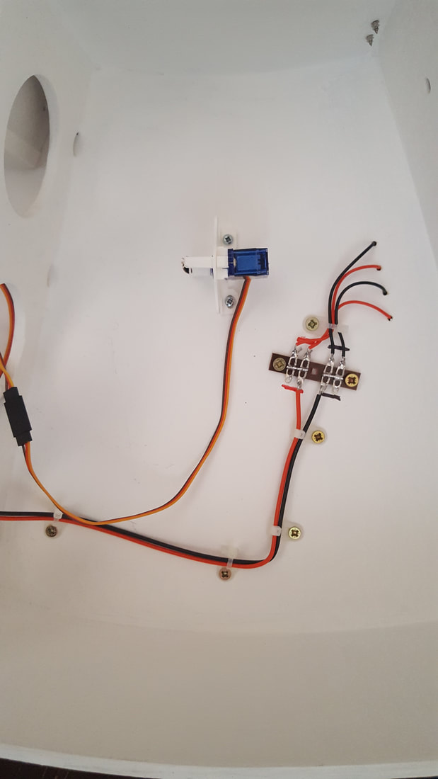
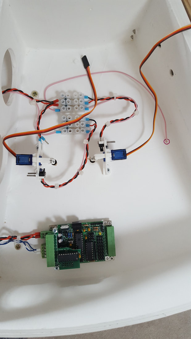
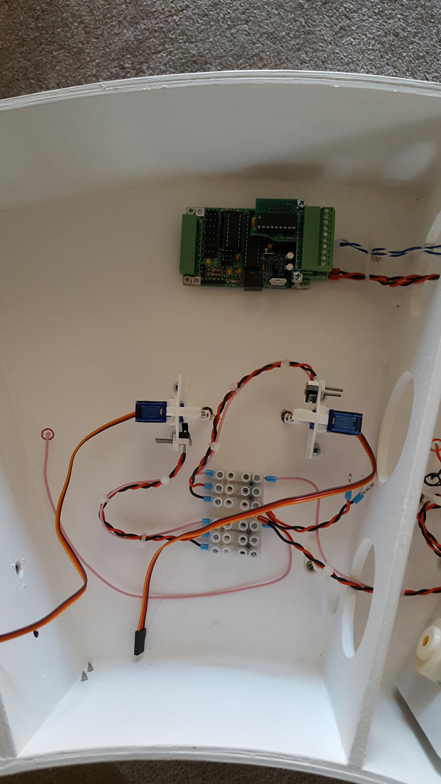
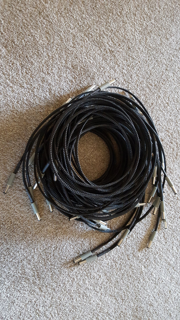
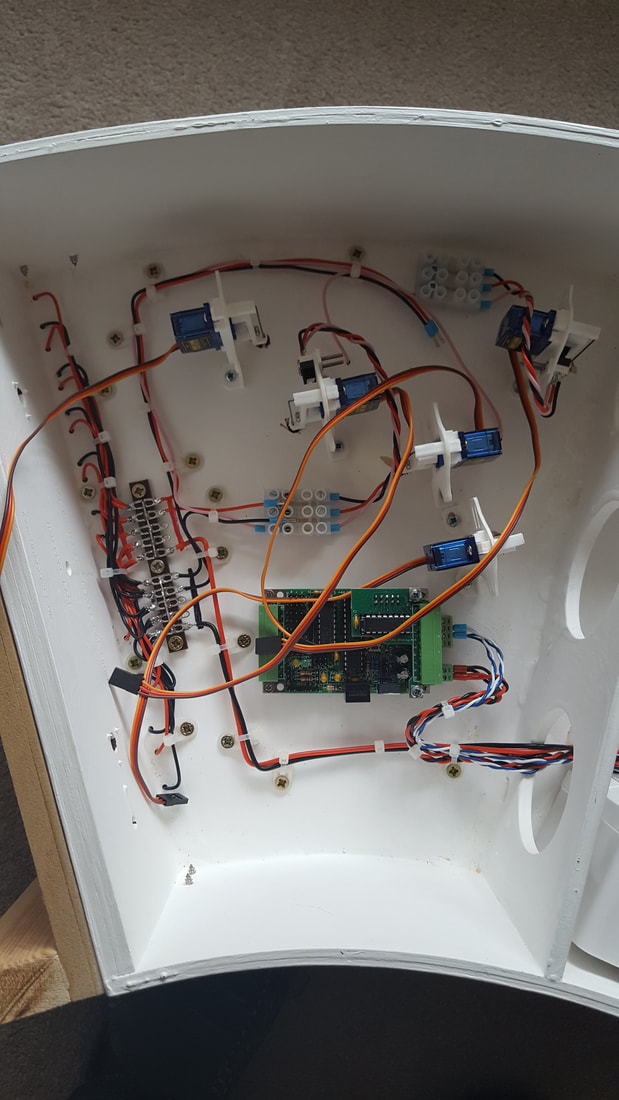
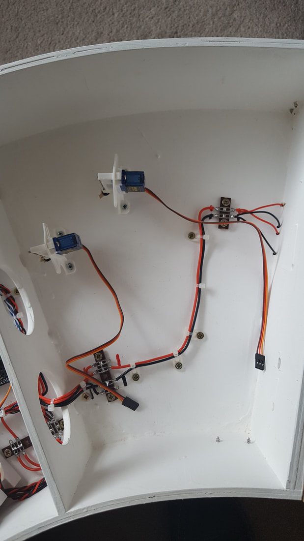
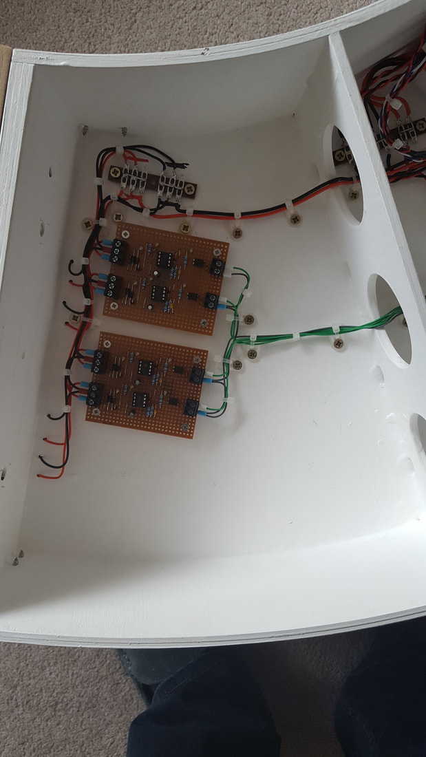
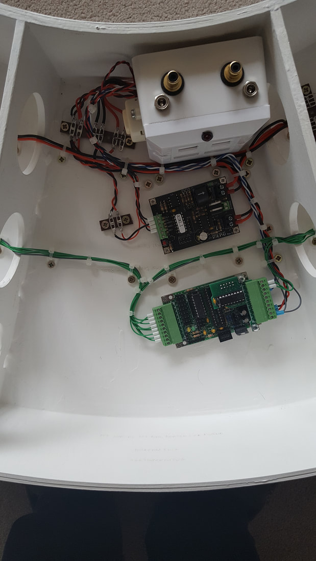
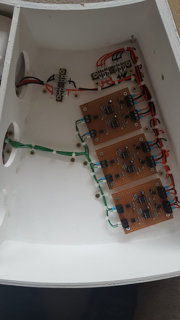
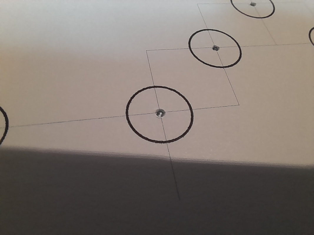
For turnout operation I am using servos, fitted to MERG (there's a trend building here!) servo mounts, and also servos with MERG signal mounts for the signals. The uncoupling magnets are DG electromagnets from Model Signal Engineering.
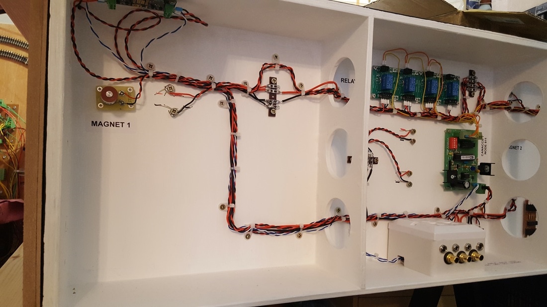
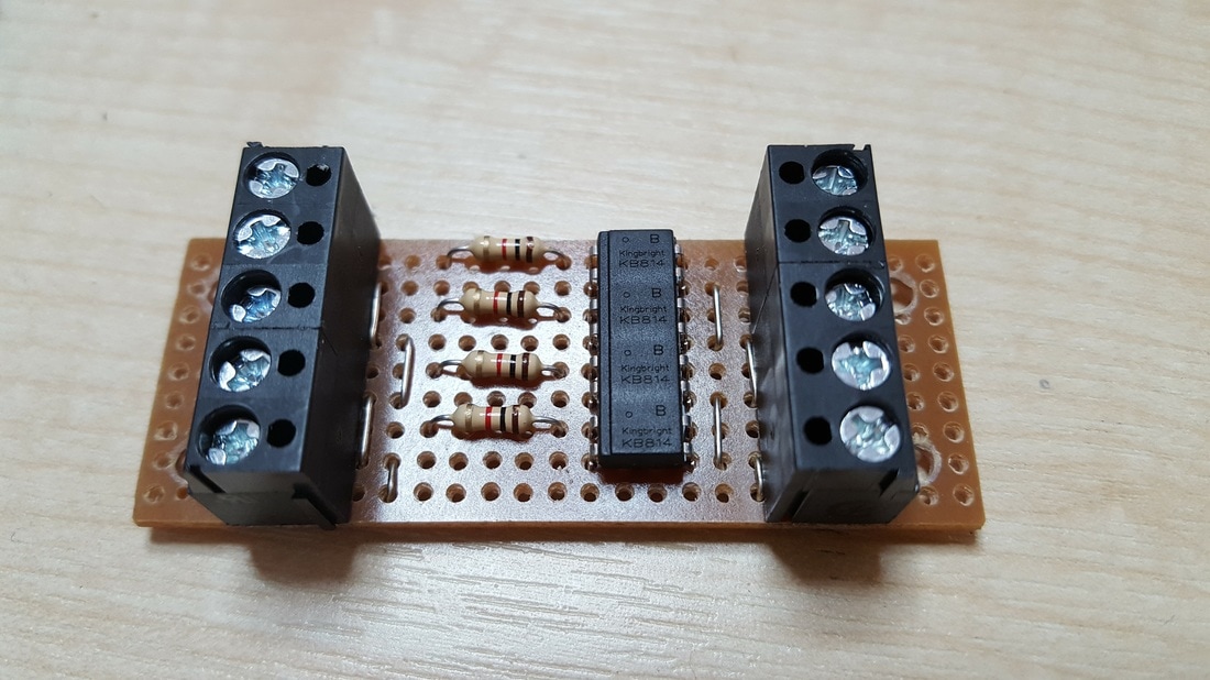
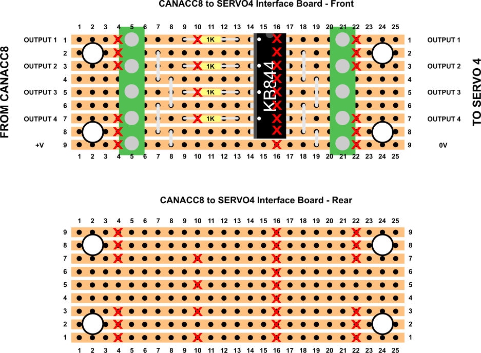
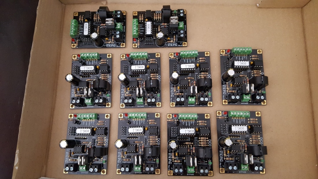
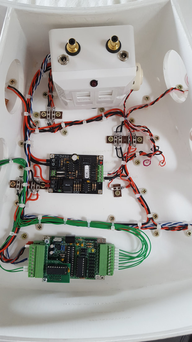
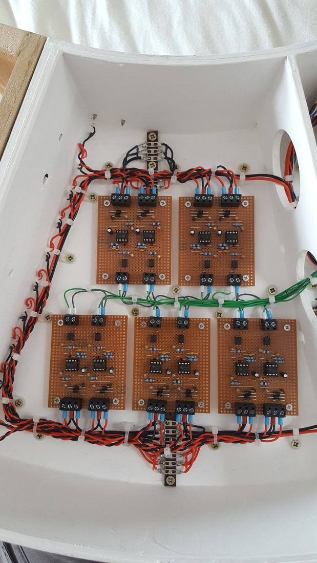
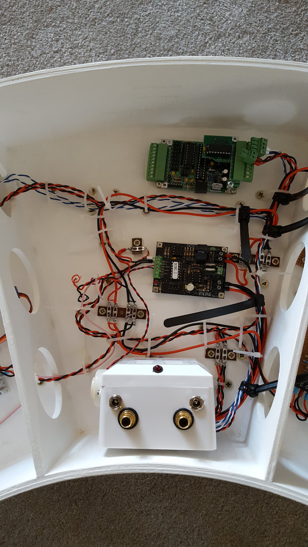
The photo shows the components required to make baseboard 2 work (except the signal servos): from the connections box at the bottom centre of the photo there will be 12VDC for the CBUS components and accessories, 12VDC for the LED lighting, DCC track bus to the rail droppers and turnout motors for polarity switching, and CBUS data. The three CANACC8s convert CBUS data into 'discretes' to trigger the SERVO4s and Relay boards, which in turn drive the turnout/signal servos and magnets respectively.
The photo shows the components required to make baseboard 2 work (except the signal servos): from the connections box at the bottom centre of the photo there will be 12VDC for the CBUS components and accessories, 12VDC for the LED lighting, DCC track bus to the rail droppers and turnout motors for polarity switching, and CBUS data. The three CANACC8s convert CBUS data into 'discretes' to trigger the SERVO4s and Relay boards, which in turn drive the turnout/signal servos and magnets respectively.
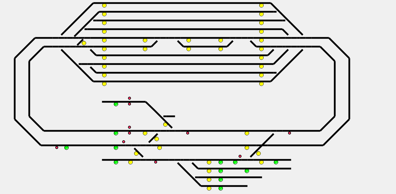
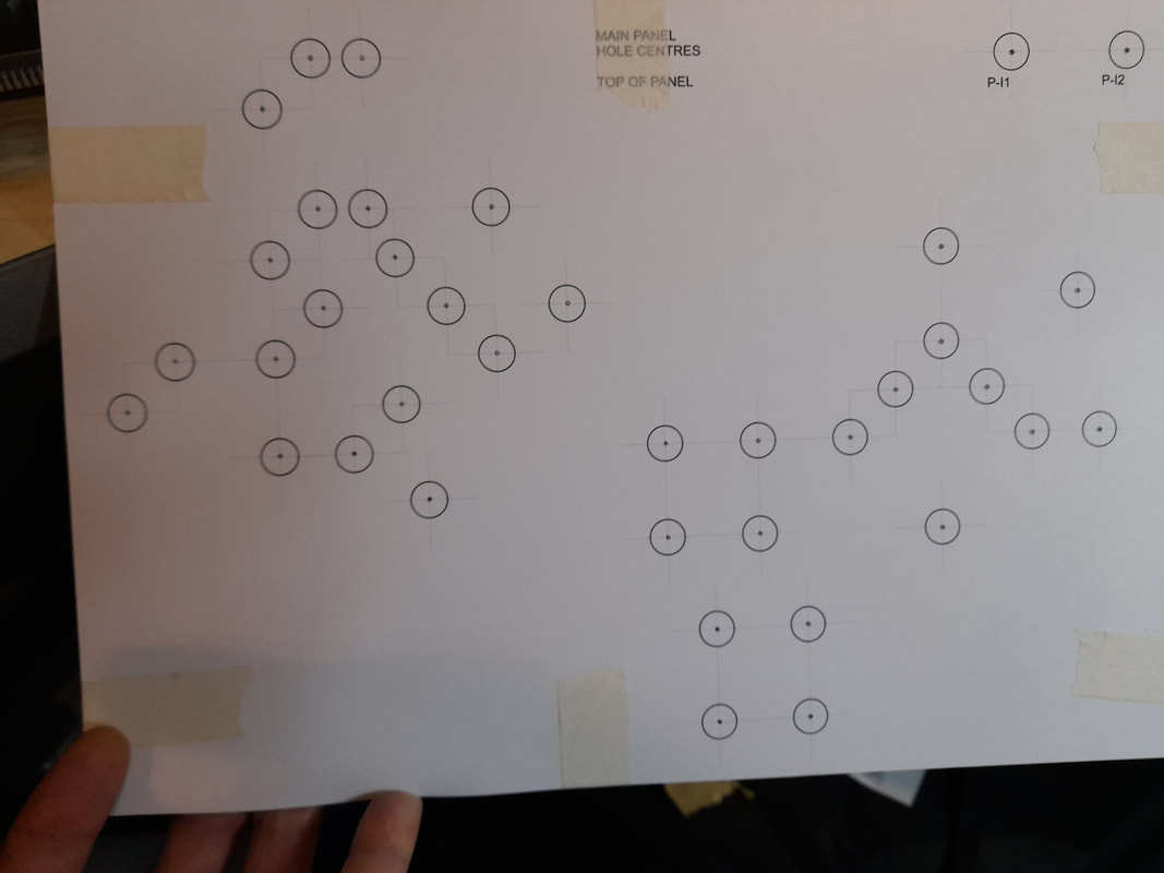
One of my 'pet hates' is watching a layout doing nothing, whilst the operator faffs with a throttle trying to change the route; I am a firm believer in using a control panel, be it a physical panel with switches and buttons, or an electronic panel on a computer. I will be building a pair of control panels, per the design below, to allow two scenic operators to control any part of the layout.
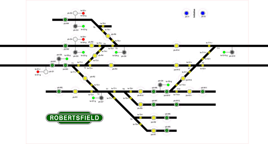
The yellow buttons will set the routes, simultaneously returning any conflicting signals to danger, the green buttons operate the electromagnets, the white buttons operate the main signals, and the black buttons operate the ground signals. The two blue buttons will be connected in series to trigger the Initialise, or "start of day" CBUS event. This simply sets the layout components and LEDS to a predetermined condition such that the layout and panel are in agreement.
The integral layout lighting uses "White" self-adhesive LED strip. I prefer this colour as, in my opinion, "Cool White" can be too clinical, "Warm White" can be too yellow, and "Daylight White" tends to melt the retinas.
The adhesive can be unreliable, so the strips were attached with Gorilla glue approximately every 3" for when the supplied adhesive inevitably dries and peels.
I have installed two strips per baseboard; one along the front edge inside the lighting unit, shining straight down, the other along the lower edge of the facia, illuminating the backscene. This stops short of the ends of the layout by approximately 6" to avoid glare on the curved backscene sections.